CODE – 02-132-942
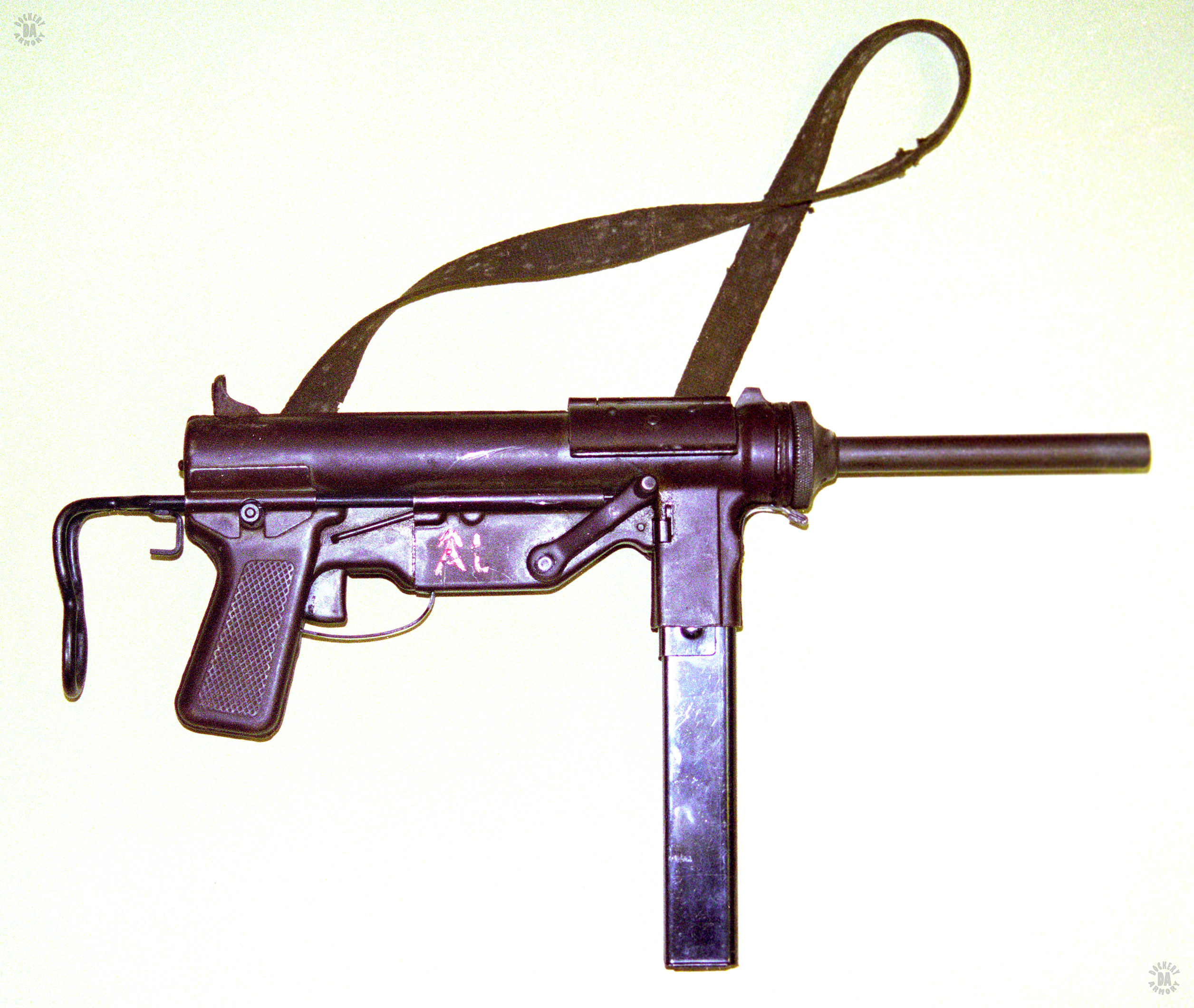
NAME – M3
NAME (NATIVE) – Gun, Submachine, Cal. .45, M3, T15, then T20 (Developmental names)
COMMON NAMES – Greasegun
COUNTRY OF ORIGIN – USA
DATE OF MANUFACTURE – 1942
CALIBER – 11.43x23mm (.45 ACP)
OVERALL LENGTH – 57.9 cm (22.8 in) Stock closed), 75.7 cm (29.8 in) Stock extended
BARREL LENGTH – 20.3 cm (8 in)
RIFLING (TYPE & TWIST) – 4 Grooves, Right hand twist 1 turn in 41 cm (16 in)
BULLET DIAMETER – 11.46 mm (0.451 in)
BULLET WEIGHT – 15 g (230 gr)
MUZZLE VELOCITY – 274 m/s (900 fps)
MUZZLE ENERGY – 561 j (414 ft/lbs)
WEIGHT (EMPTY) – 3.70 kg (8 lbs 2.5 oz)
BOLT WEIGHT – 0.91 kg (2.0 lbs)
BARREL ASSEMBLY WEIGHT – 0.61 kg (1 lb 5.3 oz)
WEIGHT (LOADED) – 4.71 kg (10 lbs 6.2 oz)
SIGHTS – Front sight – Blade, Rear sight – Peep, Set to 91 m (100 yds)
EFFECTIVE RANGE – 91 m (100 yds)
OPERATION – Blowback, fires from open bolt
TYPE OF FIRE – Full automatic
RATE OF FIRE – 90 rpm
CYCLIC ROF – 450 rpm
FEED DEVICE – 30 round box magazine, Double column, Single feed
FEED DEVICE WEIGHT (EMPTY) – 0.37 (13 oz)
FEED DEVICE WEIGHT (LOADED) – 1.01 kg (2 lbs 3.6 oz)
MAGAZINE LOADER WEIGHT – 0.121 kg (4.2 oz)
BASIC LOAD – 8 magazines (240 rounds)
LOAD WT – 8.08 kg (17 lbs 13 oz)
MANUFACTURER – General Motors, Guide Lamp Division, Anderson, Indiana
STATUS – Obsolete
SERVICE – Used in all US Military branches during WWII, some use by US Allies
In the late 1930s, early 40s, the United States could see the oncoming juggernaut that would be World War II. In the 1920s and 30s, the submachinegun was considered a specialist’s weapon and little attention had been given that weapon. With WWII looming, the US found itself armed with one type of submachinegun, the Thompson, primarily M1928A1. This was a precision-built weapon with heavy emphasis on machining techniques, making it complicated and expensive to produce. In 1940-42, a search was put forward by Army Ordnance for a new submachinegun, one that was accurate, light, and fast to make. The first weapon to meet these requirements was the Hyde-Inland design that was adopted as the M2. Production difficulties kept the Hyde-Inland M2 from reaching quotas and another design was adopted five months before the M2 was ready. That new design was the M3 submachinegun.
During the search for a new submachinegun, several foreign weapons were examined. Notably the British Sten Mk III and the German MP40. Both of these designs had been intended for mass production and were basically formed sheet metal or tubing. The United States was a world leader in the stamping and forming of metal, particularly because of the mass production capability of the automotive industry. From the issue of the requirement in July, 1942 and adopted 24 December, 1942, the M3 submachinegun took only six months to come into existence.
Part of the reason for this rapid development of the weapon was the team of designers who made it. Lead by George Hyde, a noted submachinegun designer, the Team also had Frederick Sampson, Chief Engineer for the Inland Division of General Motors corporation. Between these two men the original design of the M3 came about with Hyde leading the simplicity of operation and Sampson the idea of mass production.
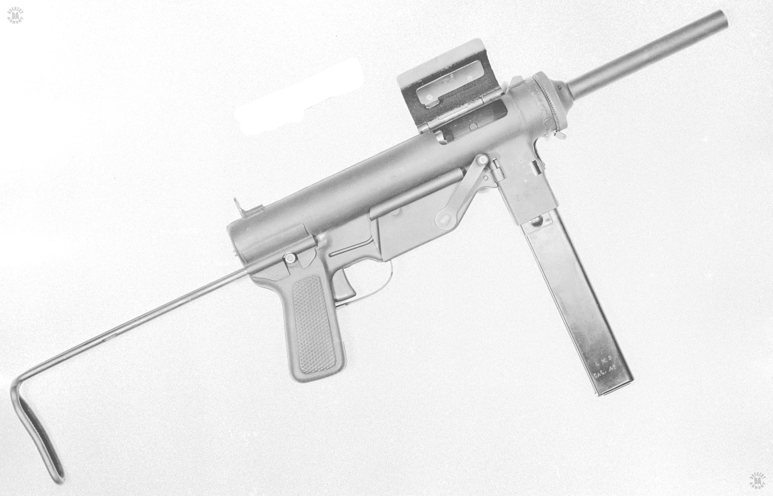
The original concept for the M3, as the developmental T15, was for a select fire weapon. That requirement was dropped and the new design, the T20, went ahead. By November, 1942 five pilot models of the T20 were ready for testing at Aberdeen Proving Ground. Simple blowback weapons, the T20 had a slow enough cyclic rate of fire that it was simple for an experienced shooter to get off single shots by trigger manipulation. Minor improvements in the design, such as enlarging the ejection port and testing continued. Weapons were fired, dropped overboard into the surf, picked up and fired. The relatively few jams that were encountered were found to be the fault of the magazine. Suggested changes in the magazine were put forward, but never really adopted and the weapon went into full production very early in 1943.
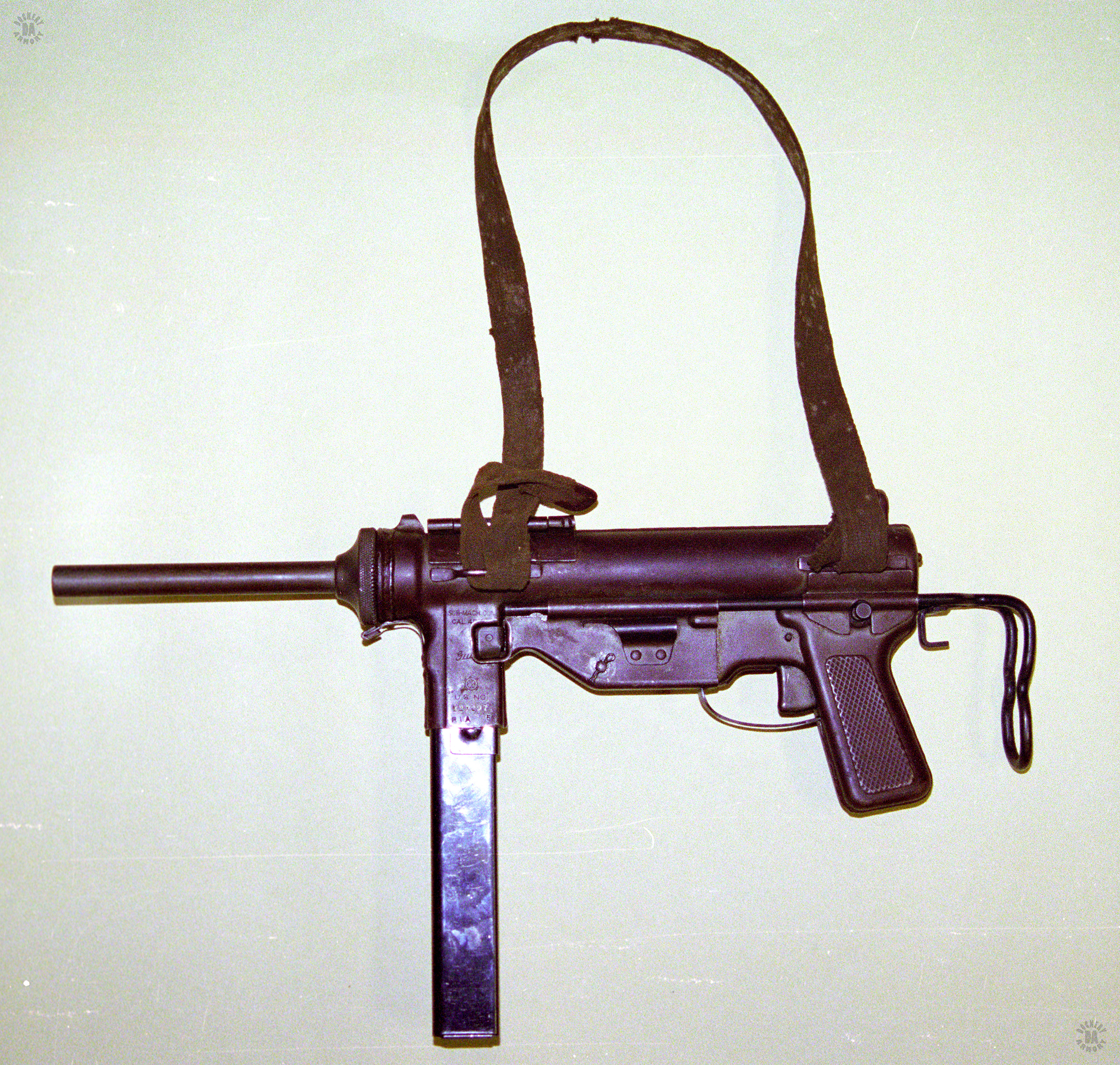
A Large part of the success of the M3 submachinegun came from the basic design of the weapon. The right and left parts of the receiver were stamped out of 1.5 mm (60 thousanths [0.060 in] thick steel and the two halves welded together. Some delays in production came up early as the welding process had to be advanced in order to prevent warping of the receiver. Additional arts were either welded on (sling swivels), pinned (trigger/sear assembly), or clipped on (housing assembly, trigger guard). The only part that screwed on was the barrel assembly.
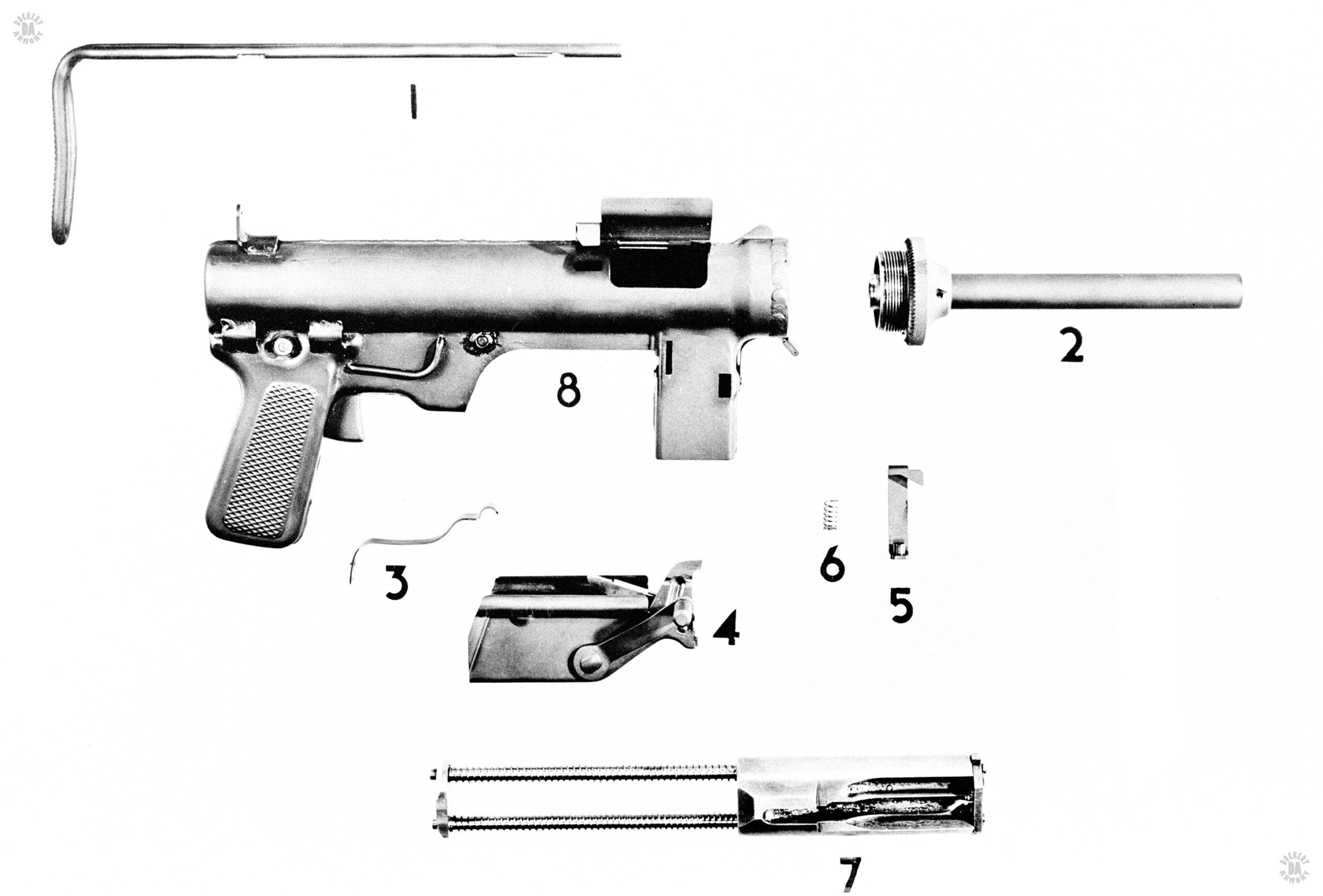
The only major parts to require machining were the bolt and barrel. The bolt rode on two rods that extended out the back of the receiver slightly and also held the recoil springs. Because of this rod and spring arrangement, the bolt did not use the body of the receiver as a travel guide as did every other successful submachinegun design in the world at the time. This gave the inside of the receiver much greater tolerances between the bolt and the body of the weapon that was normally seen and allowed the weapon to operate in very dirty conditions.
The barrel assembly required the most machining to produce, but even this was simplified by a new, innovative method of making the barrels. A length of barrel steel was drilled and reamed to the proper internal diameter. A mandrel with the rifling profile cut in reverse into its outer surface was inserted into the reamed hole. Then the entire assembly was rammed into a die, forging the outside of the barrel blank down to the correct diameter and the rifling being embossed into the bore. The 102 cm (40 inch) barrel blank would then be cut into 5 – 20 cm (8 inch) barrels. This swaging system was fast and efficient, requiring a minimum of machining to result in a finished barrel.
The safety system on the M3 was simplicity itself. With the barrel in the forward position, the ejection port cover could be closed. Then a sheet metal tab riveted to the cover would fit into a hole near the back of the bolt, locking it into place. With the bolt cocked to the rear, the cover could be closed and the safety tab would prevent the bolt from being able to travel forward. One fairly complicated part was the Housing Assembly clipped to the bottom of the receiver.
The Housing Assembly had the ejector attached to its front area, again, a simple stamped metal part. The retracting lever assembly was made up for nine parts, stamped metal, rivets, and springs, that was held within the Housing Assembly. The retracting lever was on the outside right of the Housing Assembly and was the means of cocking the bolt for firing. Pulling the lever back lifted the spring loading tip of the assembly into the bolt and forced it back against the recoil springs. Releasing the retracting handle allowed it to spring back into the forward position.
The stock of the M3 was a simple forming of a single steel rod. It slid along sheet metal guides attached to the outside of the receiver and at the top of the Housing Assembly. On the left side of the Housing Assembly was attached a clip that allowed the oiled from an M1 Carbine to be attached to the weapon.
Though it appeared to be an ugly, non-traditional weapon, the M3 submachinegun worked, and it worked well. It was easy to clean and maintain and compact, especially with its stock in the retracted position. This gave it a lot of appeal to paratroopers and vehicle drivers. The compact size of the M3 made it of particular use to tank crews, who did not have much room inside an armored vehicle. The tank crews also didn’t have to concern themselves with the weight of the loaded ammunition magazine since they didn’t have to carry them on their persons. Overall, the M3 was light, accurate, and quick to make. It also cost less than a third of what the M1A1 Thompson cost to manufacture.