CODE – 02-040-917

NAME – Bergmann MP 18/I (Schmeisser)

NAME (NATIVE) – Maschinenpistole 18.I

COMMON NAMES – MP 18

COUNTRY OF ORIGIN – Imperial Germany

DATE OF MANUFACTURE – 1917 through 1920s

CALIBER – 9x19mm

OVERALL LENGTH – 81.5 cm (32.1 in)

BARREL LENGTH – 20 cm (7.88 in)

RIFLING (TYPE & TWIST) – 6 groove, Right hand twist

BULLET DIAMETER – 9mm (0.355 in)

BULLET WEIGHT – 8.04 g (124 gr)

MUZZLE VELOCITY – 340 m/s (1115 fps)

MUZZLE ENERGY – 464 j (342 ft/lbs)

WEIGHT (EMPTY) – 4.85 kg (10 lbs 11 oz)

WEIGHT (LOADED) – 5.89 kg (13 lbs 1 oz)

SIGHTS – Front sight – inverted V-blade, Rear sight – L-shaped flip sight, V-notches for 100 and 200 meters

EFFECTIVE RANGE – 200 m (219 yds)

MAXIMUM RANGE 1600 m (1750 yds)

OPERATION – Blowback, fires from open bolt

TYPE OF FIRE – Full automatic only

RATE OF FIRE – 96 rpm

CYCLIC ROF – 350 – 450 rpm

FEED DEVICE – 32 round drum magazine

FEED DEVICE WEIGHT (EMPTY) – 0.68 kg (1 lb 8 oz)

FEED DEVICE WEIGHT (LOADED) – 1.04 kg (2 lb 6 oz)

BASIC AMMUNITION LOAD – 5 drums (160 rounds)

LOAD WEIGHT – 5.2 kg (11 lbs 14 oz)

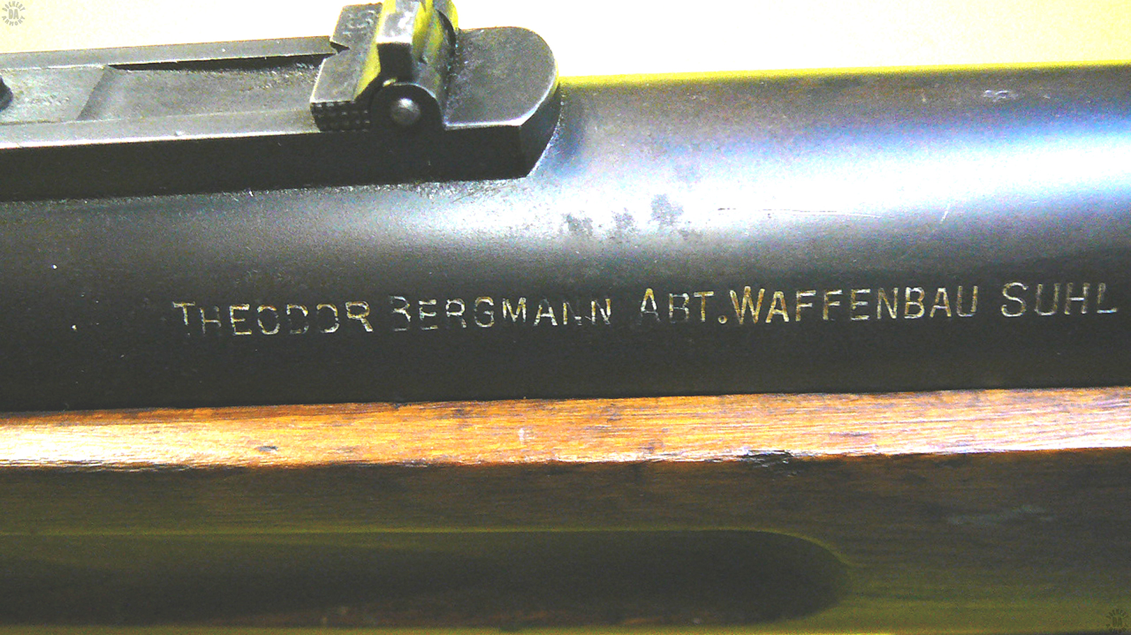
MANUFACTURER – Theodor Bergmann Abteilung, Waffenbau Suhl, Germany and Switzerland (postwar)

STATUS – Obsolete

SERVICE – German military service 1918, Post war service with German police. Second line service during WWII

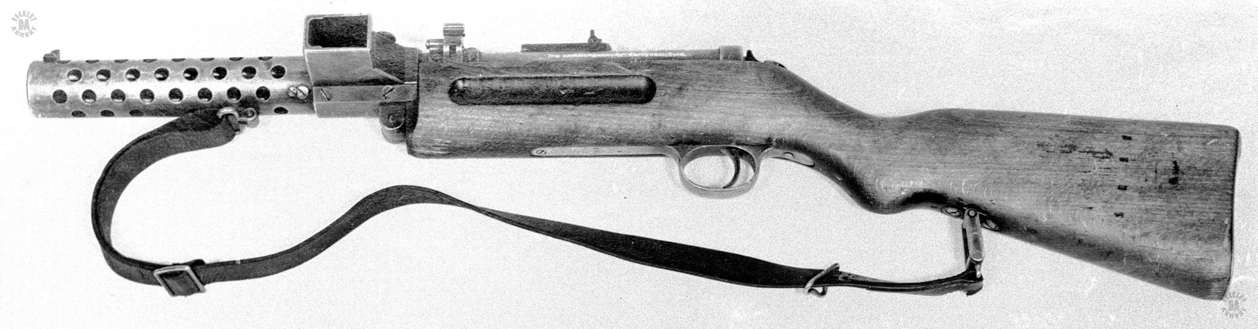
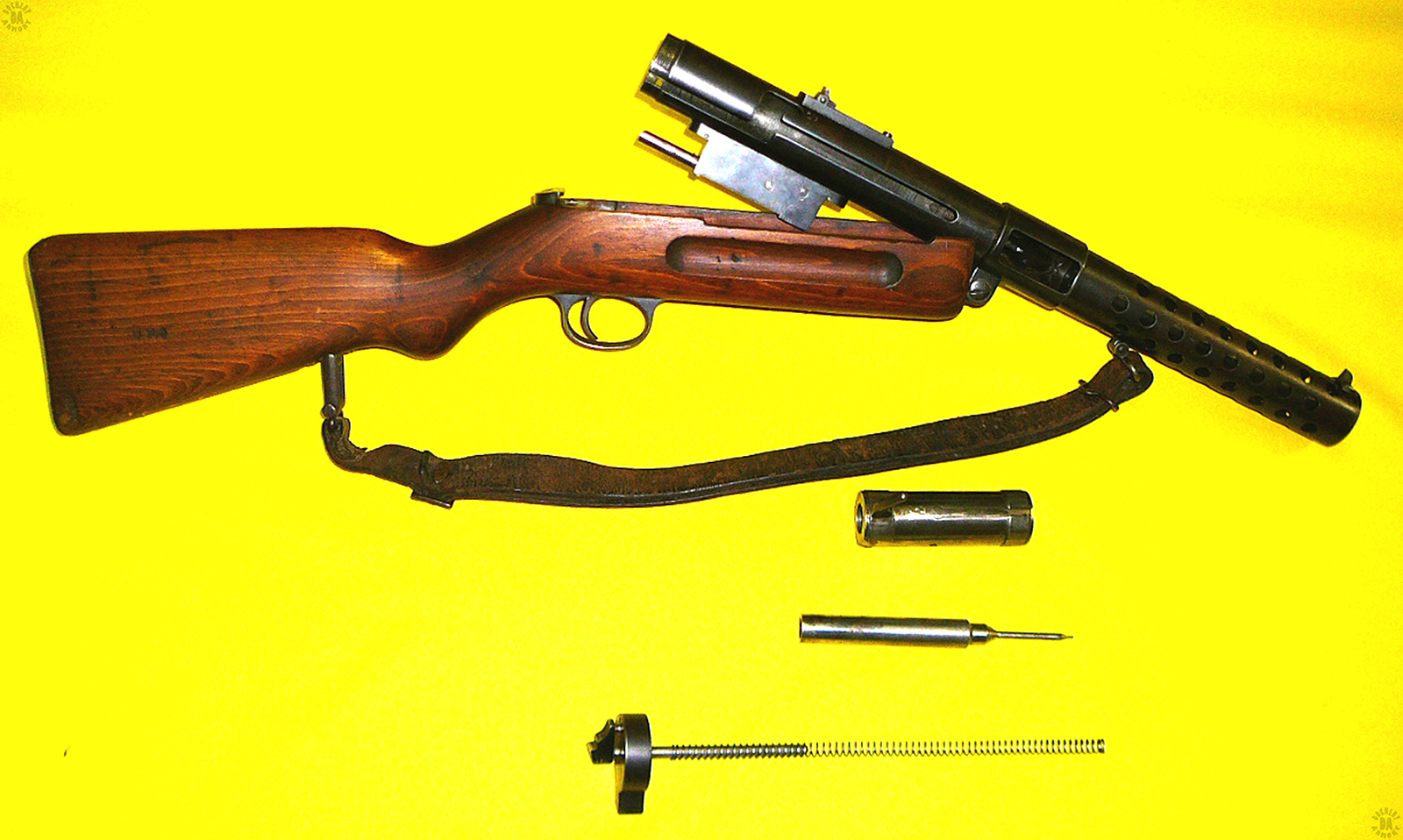
    The MP 18/I is considered by many to be the first true submachinegun. Designed in 1917, the weapon was intended to give a high volume of fire to an individual trooper in the confines of an enemy trench system. During the first use of the weapon in the Summer of 1918, it demonstrated its value as it was influential in overwhelming Allied forces during a German attack. The MP 18/I had been held back in secret until substantial numbers were available for issue.

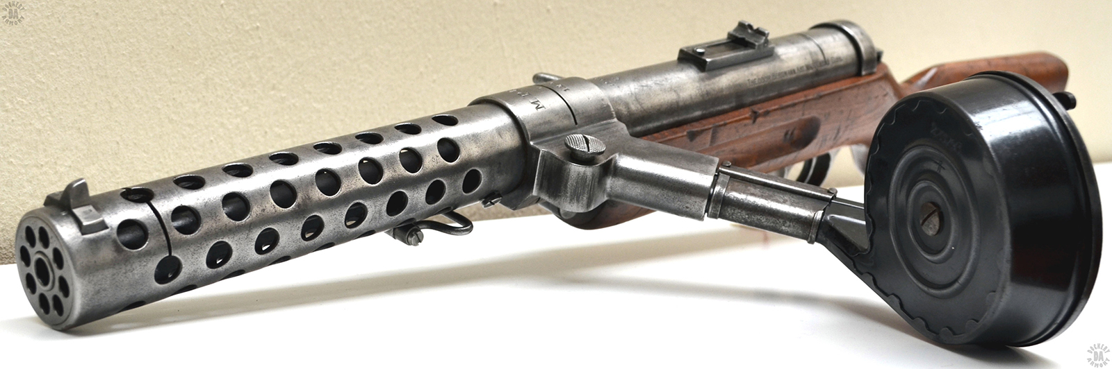
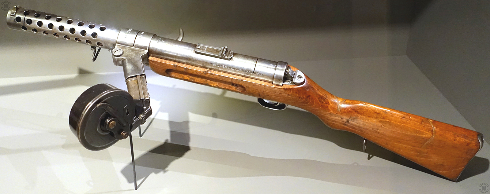
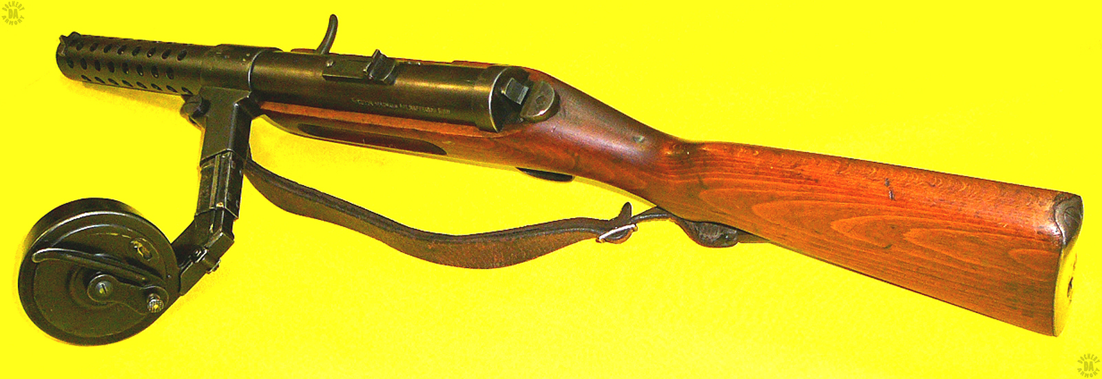
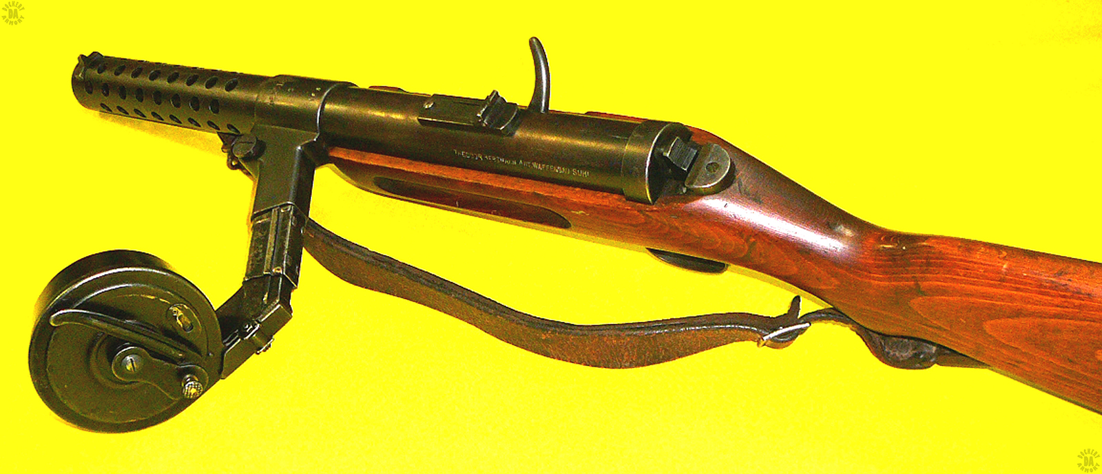
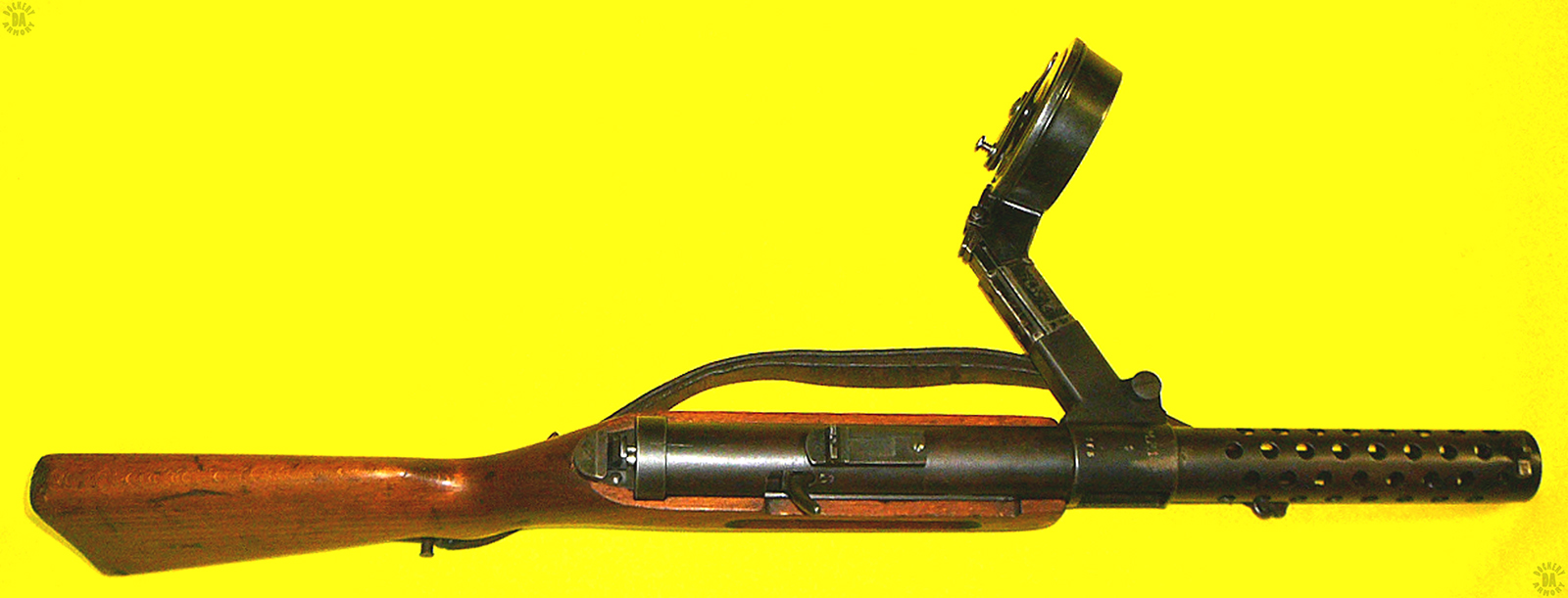
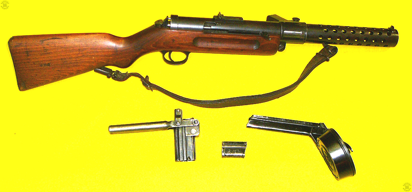
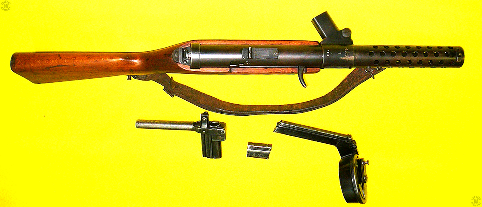
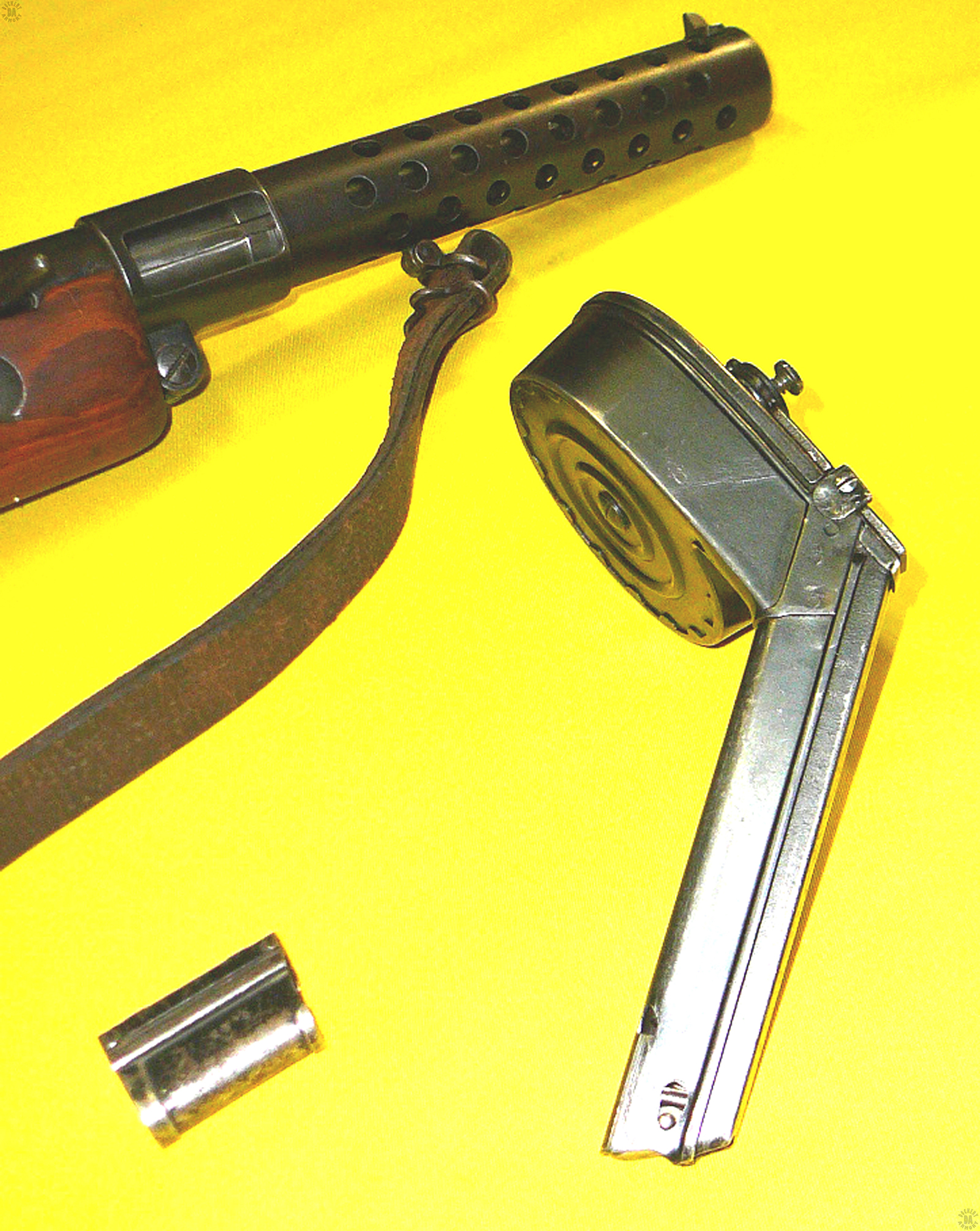
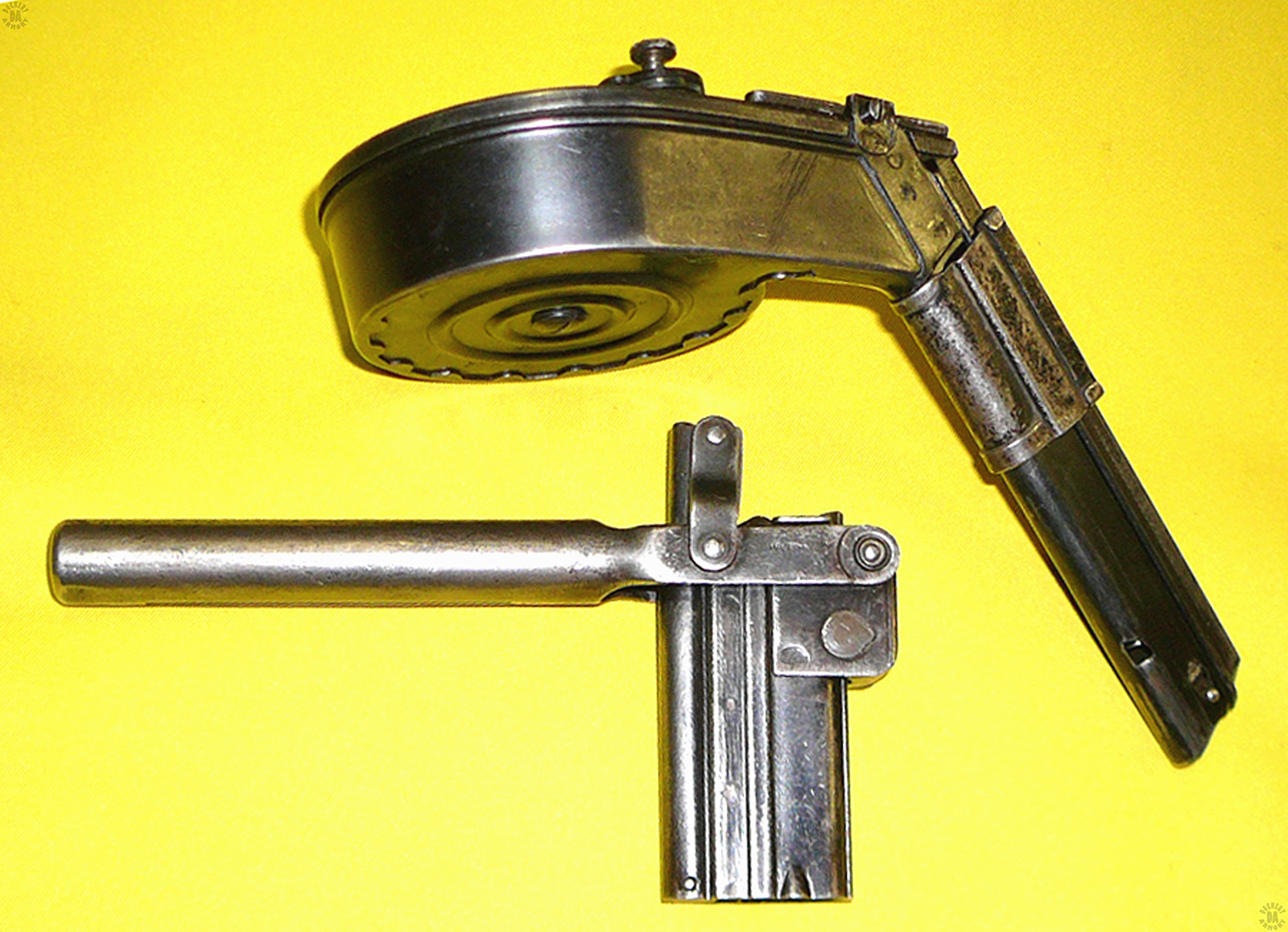
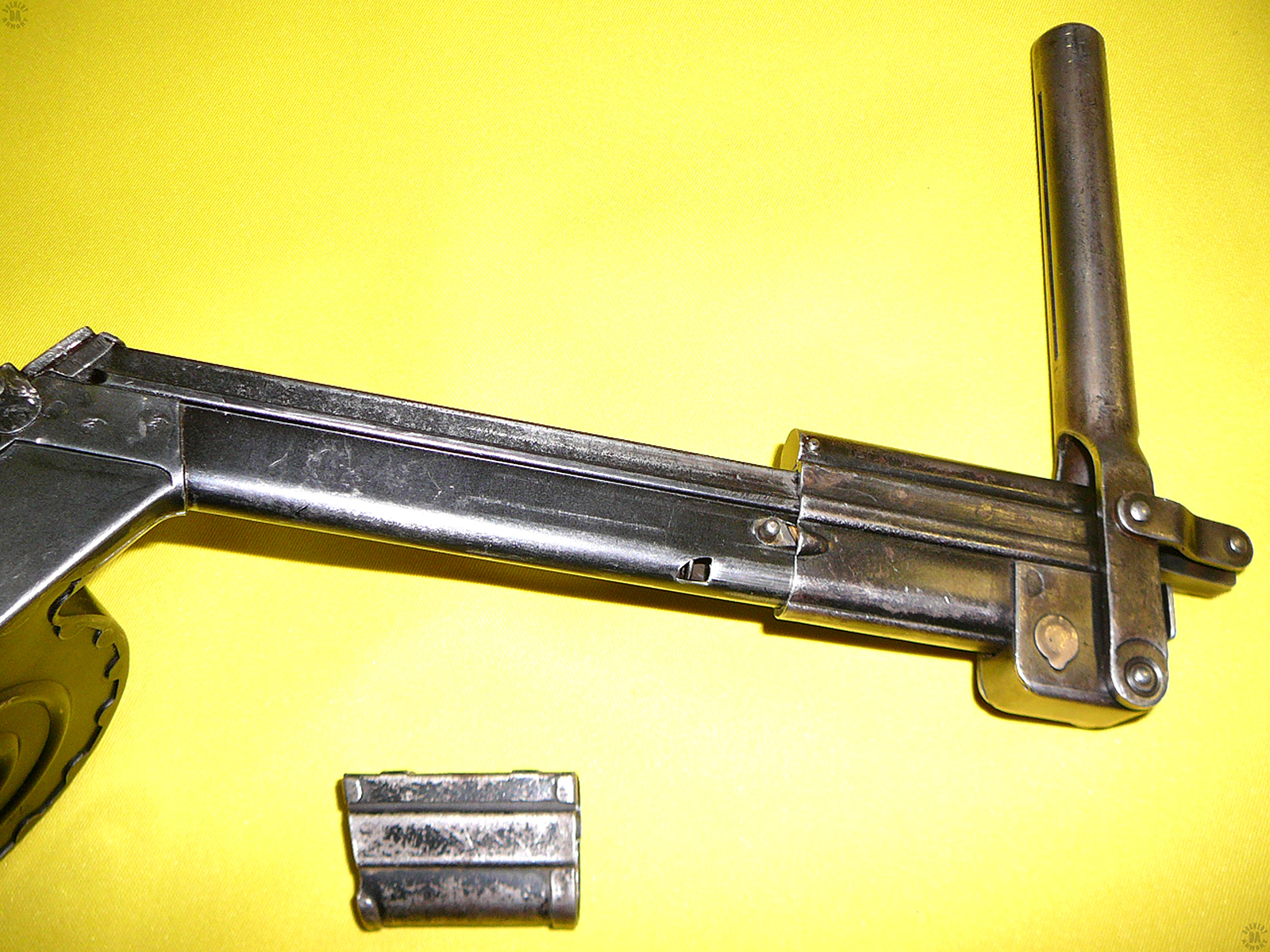
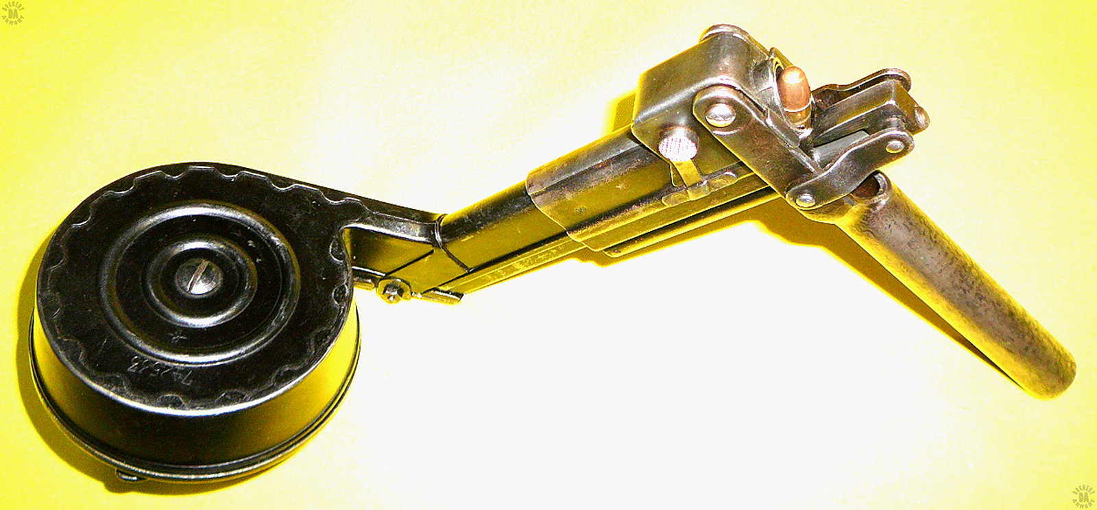
   Though the weapon was considered a success, the magazine it used was a major drawback. The 32 round (Trommelmagazin 08) drum magazine was originally designed for use with the stocked Artillery model Luger, turning it into a small semiautomatic carbine. But the sheet metal magazine was expensive to manufacture, difficult to load, and relatively fragile, particularly when stick out the left side of the weapon. To prevent inserting the magazine too far into the magazine well, a sheet metal sleeve had to be added to the base of the magazine (above the drum). Also the relatively small mainspring of the weapon gave trouble when the MP 18/I was exposed to the poor conditions found in trench warfare.

    A very influential weapon, the MP 18/I was banned for use by the German Army by the Treaty of Versailles in post-war Germany.  The weapon was allowed for issue to the German police organizations in the 1920s.

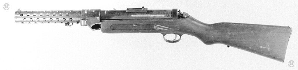
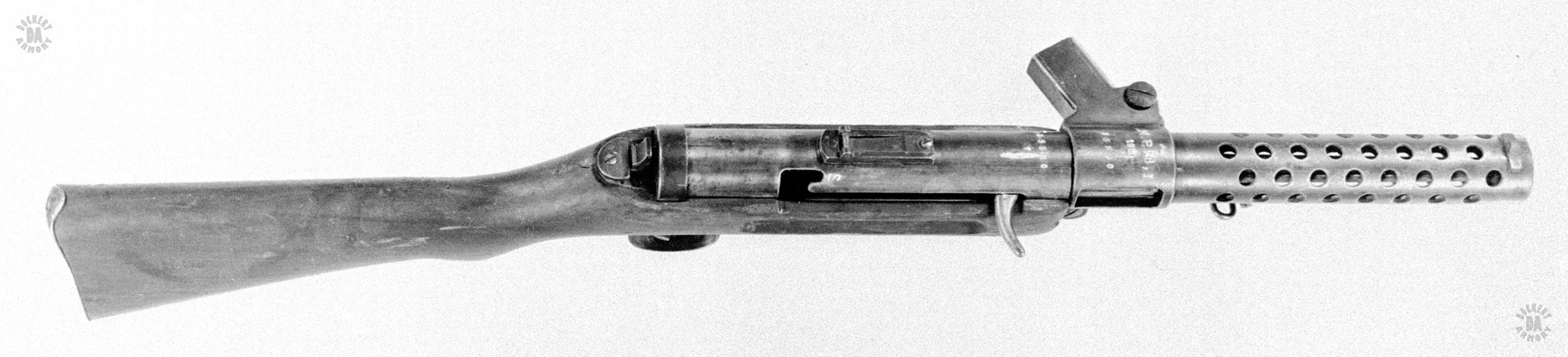
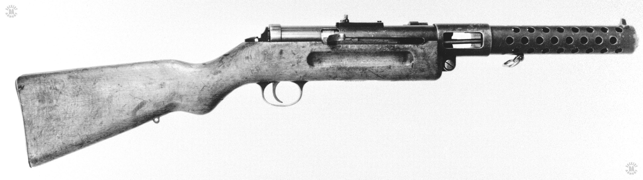
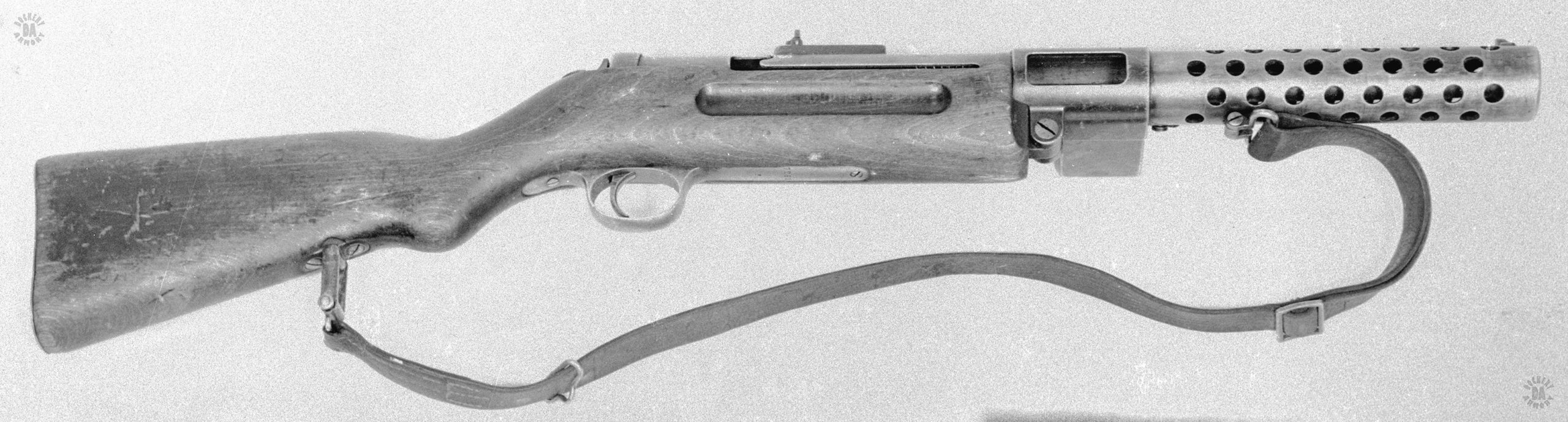
   The MP 18/I is made from finely machined parts, as were most weapons of the era, particularly those from Germany. It has a relatively thick-walled (3 millimeter) receiver. Behind the perforated barrel jacket is a machined collar that holds the magazine in place for feeding.  With a wooden carbine stock, the weapon has a smooth blued finish. For all the care in its manufacture, the basic design is simple.  The safety is an inverted L-shaped notch cut upwards near the rear of the cocking-handle slot on the right-hand side of the weapon. To use the safety, the cocking handle of the bolt is drawn to the rear and lifted up into the notch where it is held by the forward pressure of the mainspring.


This is a left side view of the Bergmann MP 18/I, considered the first true submachinegun of World War I. The marking identifying the manufacturer are filled out in white on the receiver, underneath and past the back of the rear sight. The weapon is unloaded with no magazine in the distinctive rear-slanted magazine well just ahead of and above the stock. The unusual mouth of the magazine well is so that it can accept the 32-round “Snail-drum” of the Artillery Luger. At the back of the receiver is the spring-loaded plunger that would be pressed in to release the receiver from the stock. When released, the receiver would hinge upward so that the internal components could be removed and the barrel would be accessible for cleaning. PHOTO CREDIT: US Army

An upper right side view of the Bergmann MP18/I. On the top of the magazine housing can be seen the serial number and markings for the weapon. The serial number is repeated on the receiver tube just behind the magazine housing. The markings show the German style of identifying the weapon as the M.P. 18, I. The date (1920) underneath the name indicates that this weapon was issued to the German police after World War I. The hooked cocking lever on the right of the receiver is in the forward (uncocked or fired) position. At the rear of the slot the cocking lever travels in, is the safety notch. The lever would be pulled to the rear to cock the weapon for firing and lifted into the notch, where it would move slightly forward, and be locked into the “Safe” position. The serrated take down plunger Is visible at the rear of the receiver. Just below the magazine housing, in front of the stock, is the slotted head of the receiver hinge. PHOTO CREDIT: US Army

Right side close view of the MP18/I receiver with the bolt in the cocked (open) position. The cocking lever attached to the bolt is in the rear position, underneath the safety notch. It would need to be pulled slightly more to the rear and lifted to pu the weapon on safe. PHOTO CREDIT: US Army

A lower right side view of the modified MP18-I submachinegun. The bolt and mainspring are missing on this specimen. On the left side of the new magazine housing is a straight magazine well to take a 20-round double column magazine. Because of the modification of the magazine housing from the single column snail drum magazine to the straight box double column design, the rounds had to be presented to the chamber from a single position for proper feeding. This was the weakest point in the weapons design at it continued to be used in German and other countries for decades. The hinge for opening the weapon is plain in this view underneath and part of the magazine housing. PHOTO CREDIT: US Army

In this left side view of the modified MP 18-I the new magazine housing to accept the 20-round box magazine can be plainly seen. Just above and behind the magazine housing is a special bolt lock system that was placed on MP 18 weapons that were issued to German police in post WWI Germany. The system would lock the bolt solidly in the forward position, preventing any accidental discharge if the weapon was dropped or struck solidly on the butt. PHOTO CREDIT: US Army

A front left view of an MP18/I submachine gun loaded with a 32-round Luger drum. There is a spacer sleeve on the feed neck of the drum, between the drum body and the magazine well of the submachine gun. This sleeve keeps the drum from being over inserted when reloading in the heat of battle. It can be seen that the entire weapon is manufactured from machined steel components, making for a very robust and strong, though heavy for its type, weapon. The three slit cuts across the muzzle, magazine well, and receiver, are to deactivate the weapon for display. PHOTO CREDIT: Braunschweigisches Landesmuseum

An upper left-side view of an MP18/I submachine gun, loaded with a late-model 32-round Luger drum magazine. The drum magazine is identified by the flat folding lever used to load the device. The first model drum had a telescoping round rod. The position of the curved bolt handle on the right side of the weapon indicates that the bolt is in the forward, uncocked, position. The rear sight on the top center of the round receiver has two folding leaves, one for 100 and one for 200 meters. The 200 meter leaf is in the folded position with the 100 meter leaf up for aiming. The serrated lug at the rear of the receiver would be pushed forward to unlock the receiver, allowing it to hinge open for cleaning. The three slit cuts across the muzzle, magazine well, and receiver, are to deactivate the weapon for display. PHOTO CREDIT: Braunschweigisches Landesmuseum

A left-rear view of an MP18 submachinegun fitted with a 32-round Late model Luger drum magazine. The spacer sleeve has been placed over the feed neck of the magazine, between the base section of the magazine and the magazine well. The bolt is in the forward (fired) position as seen by the curved bolt handle on the right side of the receiver. On the center top of the receiver is the base for the rear sight with the 100-meter leaf up for aiming. At the rear of the receiver is the serrated surface of the receiver catch. With the receiver unlatched, the upper receiver would hinge up so that the internal parts can be removed for cleaning. PHOTO CREDIT: WARREN WHEATFIELD

A left-rear view of an MP18 submachinegun fitted with a 32-round Late model Luger drum magazine. The spacer sleeve has been placed over the feed neck of the magazine, between the base section of the magazine and the magazine well. The bolt is in the rearmost, cocked, position as seen by the curved bolt handle on the right side of the receiver. The bolt handle has been lifted up into the safety notch in the upper side of the handle slot. On the center top of the receiver is the base for the rear sight with the 100-meter leaf up for aiming. At the rear of the receiver is the serrated surface of the receiver catch. The catch would be pressed in against spring pressure to unhook from the flat side of the retaining plate attached to the stock. With the receiver unlatched, the upper receiver would hinge up so that the internal parts can be removed for cleaning. PHOTO CREDIT: WARREN WHEATFIELD

Looking down at the top right side of the MP18 submachinegun fitted with a 32-round Late model Luger drum magazine. The magazine has been blocked from over-insertion into the magazine well of the weapon by a spacer sleeve placed over the feed neck of the drum. The rear sight on the top center of the cylindrical receiver has a simple, flip-leaf sight with both the 100 and 200-meter leaf up. The curved cocking lever on the underside (right side) of the receiver is in the fully cocked position with the lever rotated up into the safety notch. Ahead of the notch is the large “S” (safety) marking. PHOTO CREDIT: WARREN WHEATFIELD

The right side of an MP18 above the 32-round Luger magazine and accessories used to load it. On the lower left is a 32-round Late model Luger drum, originally intended for use with the Model 1914 Artillery Luger pistol. In the lower center of the picture is the spacer sleeve used to keep the long feed neck of the drum magazine from being over-inserted into the magazine well. The formed sheet metal spacer slips over the neck of the drum magazine. On the lower left is the loading tool necessary for loading the drum magazine with ammunition. PHOTO CREDIT: WARREN WHEATFIELD

The top view of an MP18 above the 32-round Luger magazine and accessories used to load it. The angle of the magazine well can be seen on the left side of the weapon. The angle of the magazine well matches the angle of the feed neck of the drum magazine so that the round is presented straight on to the chamber of the weapon. On the lower right is a 32-round Late model Luger drum, originally intended for use with the Model 1914 Artillery Luger pistol. In the lower center of the picture is the spacer sleeve used to keep the long feed neck of the drum magazine from being over-inserted into the magazine well. The formed sheet metal spacer slips over the neck of the drum magazine. On the lower left is the loading tool necessary for loading the drum magazine with ammunition. PHOTO CREDIT: WARREN WHEATFIELD

The right side of the Late model luger drum magazine is uppermost in this picture. Loaded rounds would extend the length of the feed neck of the drum and continue around the circumference of the drum body. A very strong springs drives the column of rounds, requiring a special loading tool to properly fill the magazine. On the lower left is the spacer sleeve that makes using the drum magazine to load the MP18/I much easier and faster. Without the sleeve on the feed neck, the magazine could be carefully loaded into the weapon, the magazine catch seating in the small notch on the front edge of the feed neck, just below the top of the magazine. But in the rush of combat, the drum could easily be over-inserted and a jam result, taking the weapon out of action for a few moments. PHOTO CREDIT: WARREN WHEATFIELD

The late-model 32-round Luger drum magazine with the spacer sleeve for the MP18/I submachine gun in place at the bottom of the feed neck. The special loading tool for filling the magazine is at the bottom of the picture. PHOTO CREDIT: WARREN WHEATFIELD

The late-model 32-round Luger drum magazine with the loading tool being placed over the feed neck of the magazine. The loading tool would be slipped further down the feed neck of the drum magazine until it caught on the magazine catch. Part of the mag catch is the round piece flush with the surface of the loading tool. Just below the lever. The magazine catch of the feed neck is just a short distance below the bottom of the loading tool. The spacer sleeve to properly use the drum magazine with an MP18/I is at the bottom of the picture. PHOTO CREDIT: WARREN WHEATFIELD

The late-model 32-round Luger magazine, also called a “Snail Drum” magazine, with the loading tool locked into place in the top of the magazine. A round has been slipped into the top of the magazine. The lever extending out the back of the tool would be lifted up to force the round down into the magazine, against spring pressure. With the round pressed down by the loading tool, there is room to slip a fresh round of ammunition in place. The lever is brought back up, the new round seated further back into the magazine, and then the process repeated. PHOTO CREDIT: WARREN WHEATFIELD

The right -side of an MP18/I field stripped for maintenance. The receiver has been hinged up from the lower stock and the bolt assembly removed. The end cap, latch, and mainspring assembly are at the bottom of the picture. Above the mainspring is the firing pin assembly. At the center of the picture is the bolt assembly with the cocking handle sticking straight up. The bolt would be drawn back in the slot of the side of the receiver, then rotated down, and drawn back further to clear the receiver for disassembly. PHOTO CREDIT: WARREN WHEATFIELD

The left side of the MP18/I receiver showing the manufacturer’s markings. The manufacturer was “THEODOR BERGMANN” ABT. [Abteilung] WAFFENBAU SUHL. The serial number and name of the weapon are on top of the receiver, at the magazine well. PHOTO CREDIT: WARREN WHEATFIELD