CODE – 02-131-941

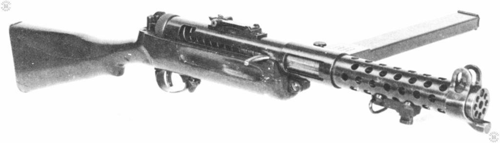
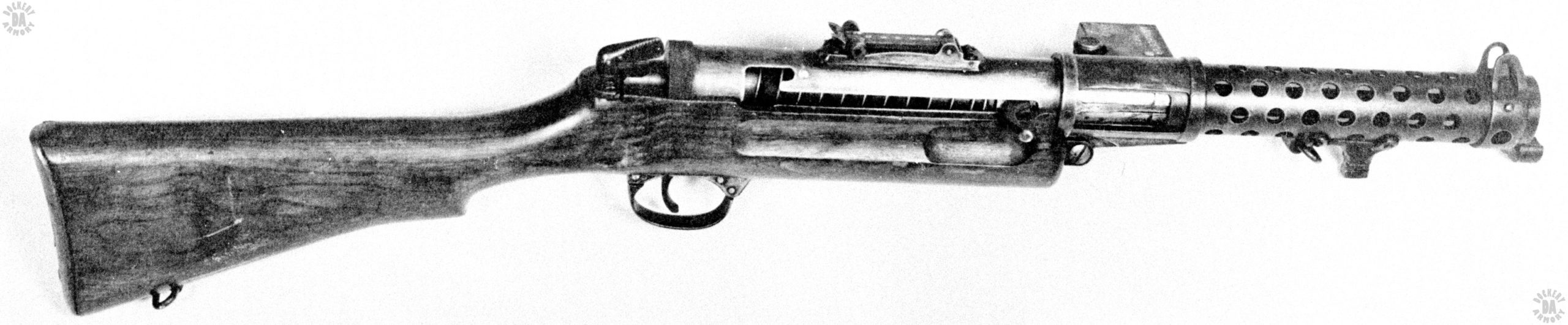
NAME – Lanchester Mk I (Mk I*)

NAME (NATIVE) Lanchester Machine Carbine 9-mm Mk I

COUNTRY OF ORIGIN – Great Britain (Germany)

DATE OF MANUFACTURE – 1941 (Mk I* 1942)

CALIBER – 9x19mm

OVERALL LENGTH – 85.1 cm (33.5 in)

BARREL LENGTH – 20 cm (7.9 in)

RIFLING (TYPE & TWIST) – 6-groove, Right hand twist, 1 turn in 25 cm (9.8 in)

BULLET DIAMETER – 9.02 mm 0.355 in

BULLET WEIGHT – 7.45 g (115 gr)

MUZZLE VELOCITY – 351 m/s (1150 fps) Mk1Z

MUZZLE ENERGY – 458 j (338 ft/lbs)

WEIGHT (EMPTY) – 4.35 kg (9 lbs 10.5 oz)

WEIGHT (LOADED) – 5.34 kg (11 lb 13.5 oz) with 50 round magazine

SIGHTS – Front – Protected blade, Rear – Tangent sight with U notch, Graduated from 91 m (100 yds) to 548 m (600 yds) in 91 m (100 yd) increments

EFFECTIVE RANGE – 183 m (200 yds)

OPERATION – Blowback, fires from open bolt

TYPE OF FIRE – Selective fire, Semi and Full automatic. Mk I* – Full automatic only

RATE OF FIRE – 40 rpm (Semi), 100 rpm (Full)

CYCLIC ROF – 600 rpm

FEED DEVICE – 50 round box magazine, double column, single feed

FEED DEVICE WEIGHT (EMPTY) – 0.37 kg (13 oz)

FEED DEVICE WEIGHT (LOADED) – 0.99 kg (2 lb 3 oz)

BASIC LOAD – 6 magazines (300 rds)

LOAD WT – 5.94 kg (13 lb 2 oz)

MANUFACTURER – Sterling Company, Dagenham, Essex, England

STATUS – Obsolete

SERVICE – British and Commonwealth Navies

     Prior to World War II, the British Military had decided that submachinegun, or what they called “Gangster Guns,” had no value in modern combat. With the disaster and losses at Dunkirk, the opinions of military commanders had changed. They wanted submachineguns, as many as they could get and as quickly as possible. Over 300,000 M1928 Thompsons were ordered from the United States, but the German U-Boat campaign put 200,000 of those weapons on the bottom of the Atlantic Ocean.

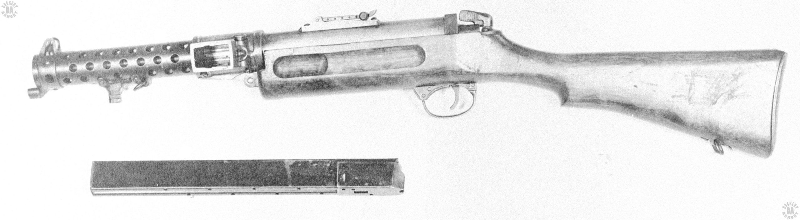
     There was no real time available for research into a new submachinegun. The answer to part of the demand would be to copy an existing design. Specimens of the German MP28/II were obtained by the British Consul General in Addis Ababa and forwarded to Enfield and the design team of Major Reginald V. Shepherd and Harold J Turpin. They were to develop a copy of the supplied weapons, making them as easy as possible to manufacture and using the least amount of critical materials. When the War Department assigned the manufacture of the new weapons to the Sterling Engineering Co. of Dagemham, Essex, another engineer, George Lanchester, led several others in the task of organizing the manufacture of the new weapon.

     Several modifications of the original German design were incorporated into the “9mm Schmeisser carbine” project by Lanchester. Among these changes was the addition of a bayonet lug on the barrel jacket, the changing of the wooden butt to match that of the Lee Enfield rifle, and the changing of the steel magazine housing to one made from cast bronze. The magazine for the new weapon was based on that of the original MP28, which was one of the great errors of the design. The double-column, single-feed design by Hugo Schmeisser was always a weak point as the magazine couldn’t absorb dirt and debris without jamming. The magazine also needed a loading tool to overcome the pressure of the magazine spring. But since the magazine had been adopted by the Germans, the British would as well. Additionally, since the desired but unavailable Thompson used a 50 round drum magazine, the new British weapon would have a 50 round box magazine developed for it.

     The resulting weapon was considered to be unbalanced and difficult to handle, especially when compared to the MP28/II. The bayonet mounts were intended to accept the 1907-pattern bayonet for the No. I Mk III Enfield rifle. The bayonet was 55.2 cm (21.75 in) long. When mounted on the submachinegun, the 43.2 cm (17 in) blade stuck out past the muzzle of the weapon, adding half again to the overall length of the submachinegun.

     The new design was accepted immediately due to the pressures of war. Very soon after the adoption of what was now the Lanchester Mk I, modifications were made. The biggest change was the removal of the selector switch, changing the weapon to full automatic fire only. The shape and length of the bolt cocking lever was modified. The new weapon was the Lanchester Mk I* (Mk I Star).

     The Lanchester was expensive to produce and not economical in terms of time and equipment needed to make it. But it did work and it also gave members of the design team a good deal of very important experience in producing such a weapon. As new designs became available, the Lanchester was issued to the Royal Navy, where it’s weight and size was less of a restriction.


This is an early-production Lanchester Mark I submachinegun complete with the modifications requested by the Royal Navy. The weapon has a full wooden stock shaped like that of the No I Mk III Lee Enfield rifle. The muzzle of the barrel is surrounded by a separate front sight protector with a bayonet lug. Further back on the bottom of the perforated barrel jacket is the standard for mounting 1907-pattern bayonet as for the No. I Mk III Enfield rifle. The bayonet standard also has the front sling swivel as a component. The bolt has the curved cocking handle of the original models and is in the forward (fired) position. At the rear of the cocking handle slot is the safety slot that required the bolt to be fully drawn to the rear and lifted up and slightly forward to secure the bolt. Underneath the magazine housing is the hinge point where the two major parts of the weapon swing open when the rear catch, just visible behind the knurled knob at the rear of the receiver, is unlocked. The mechanism on the front of the trigger guard is the selector switch. When the lever on the front of the selector is set to point down, as it is in this picture, the weapon is set on semiautomatic fire. With the lever rotated and pointing up towards the receiver, the weapon is set to full automatic fire. On top of the receiver is the long tangent sight that was only found on the Mk I model. PHOTO CREDIT: US ARMY

This is a left side view of a Lanchester Mk I converted to the Mk I* version. The primary difference between the Mk I and the Mk I* is that the latter is made for full-automatic fire only. The two pins on the front of the trigger guard show where the selector mechanism was removed and a cover secured over the opening. This specimen has the early-model tangent rear sight on top of the receiver. The rear catch that unlocks the upper and lower receivers is plainly seen as the serrated lever at the rear of the receiver. The magazine laying across the bottom of the picture is the standard 50-round model produced at the request of the Royal Navy. PHOTO CREDIT: US ARMY

An upper right-side view of the Lanchester Mk I*. The bolt is in the forward (fired) position and the safety notch can be plainly seen at the rear of the cocking handle slot. On top of the receiver is the large tangent adjustable rear sight. This was replaced with a much simpler rear sight on later production models. On the front of the trigger guard can be seen the rivets that secure the cover over the hole that resulted when the select fire switch was removed. On the very rear of the wooden stock can be seen part of the brass butt plate that greatly strengthens the rear of the stock. PHOTO CREDIT: US ARMY