NAME (NATIVE) – Maschinenpistole 40

COMMON NAMES – Schmeisser

COUNTRY OF ORIGIN – Germany

DATE OF MANUFACTURE – 1942 to 1945

CALIBER – 9x19mm

OVERALL LENGTH – 63 cm (24.8 in) (Stock folded), 83.3 cm (32.8 in) (Stock open)

BARREL LENGTH – 25.1 cm (9.9 in)

RIFLING (TYPE & TWIST) – 6 groove, Right hand twist

BULLET WEIGHT – 8.04 g (124 gr)

BULLET DIAMETER – 9mm (0.355 in)

MUZZLE VELOCITY – 381 m/s (1250 fps)

MUZZLE ENERGY – 583 j (430 ft/lbs)

WEIGHT (EMPTY) – 4.02 kg (8 lbs 14 oz)

WEIGHT (LOADED) – 4.67 kg (10lbs 5 oz)

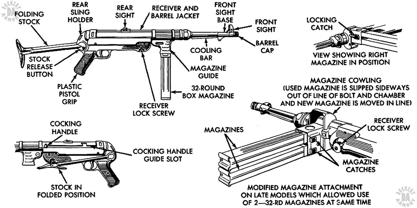
SIGHTS – Front – Blade, Rear open U-notch, flip sight for 100 and 200 meters (109 and 218 yds)

EFFECTIVE RANGE – 200 m (218 yds)

OPERATION – Blowback, fires from open bolt

TYPE OF FIRE – Full automatic only

RATE OF FIRE – 96 rpm

CYCLIC ROF – 500 rpm

FEED DEVICE – 32 round box magazine, double-column, single position feed

FEED DEVICE WEIGHT (EMPTY) – 0.26 kg (9 oz)

FEED DEVICE WEIGHT (LOADED) – 0.65 kg (1 lb 7 oz)

MAGAZINE LOADER WEIGHT 0.15 kg (5.3 oz)

BASIC AMMUNITION LOAD – 6 magazines (192 rds)

LOAD WEIGHT – 3.9 kg (8 lbs 10 oz)

MANUFACTURER – ERMA Erfurter Maschinenfabrik B. Geipel GmbH, Erfurt, Germany, C.G. Haenel Waffen-und Fahrradfabrik AG, Suhl, Germany, Steyr-Daimler-Puch, A.G. Werk, Steyr, Osterreichische (Austria). And a number of subcontractors who produced parts.

STATUS – Obsolete, May still be found in guerilla hands throughout the world

SERVICE –– Extensive issue and use throughout all of the German forces during WWII. Post World War II saw widespread use of the MP40, limited only by the numbers produced, in Chinese and other Asian countries as well as South and Central America with both military and police forces.

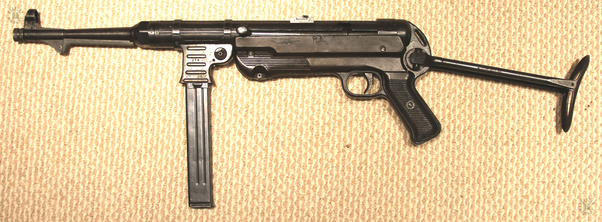
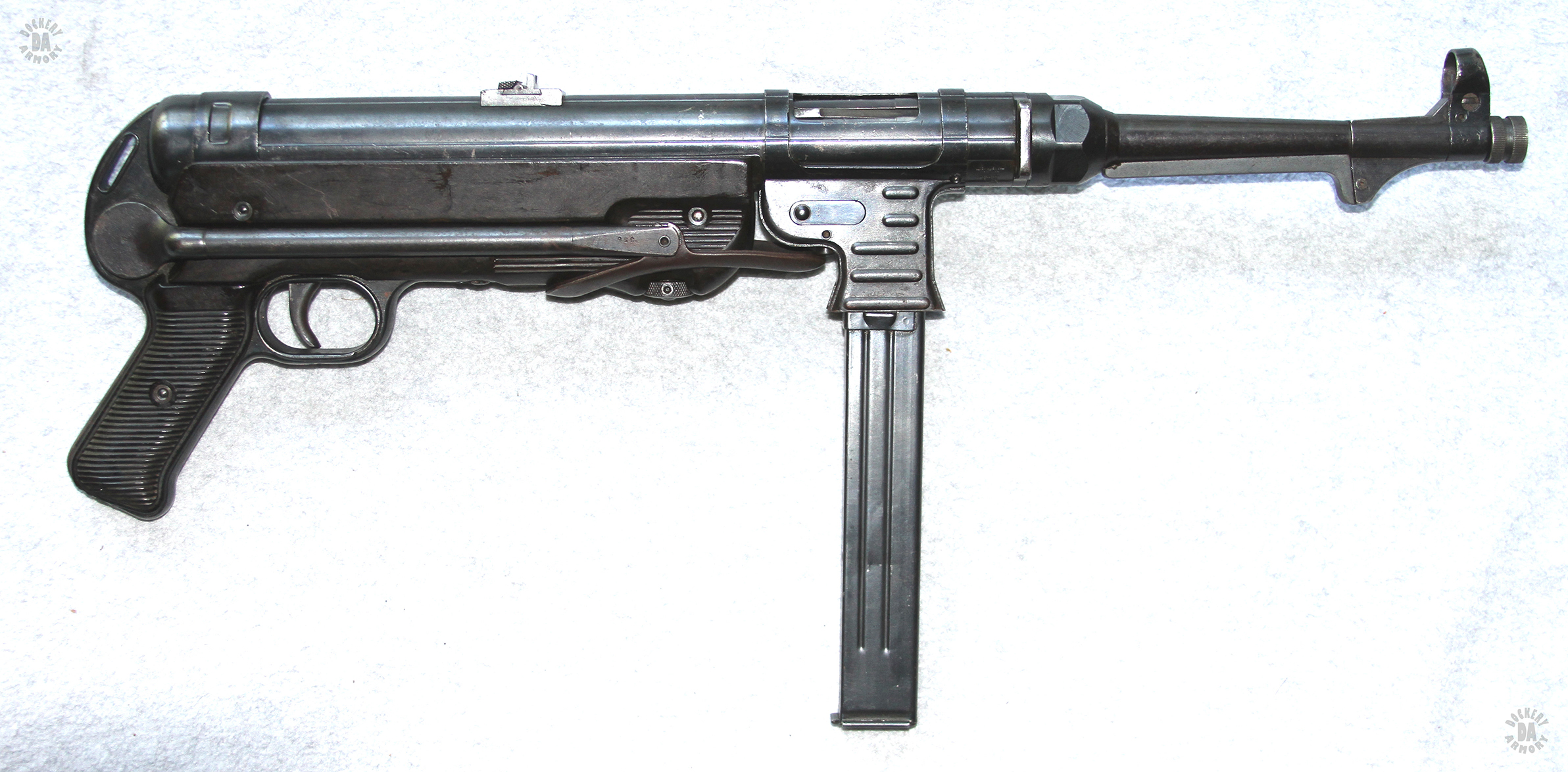
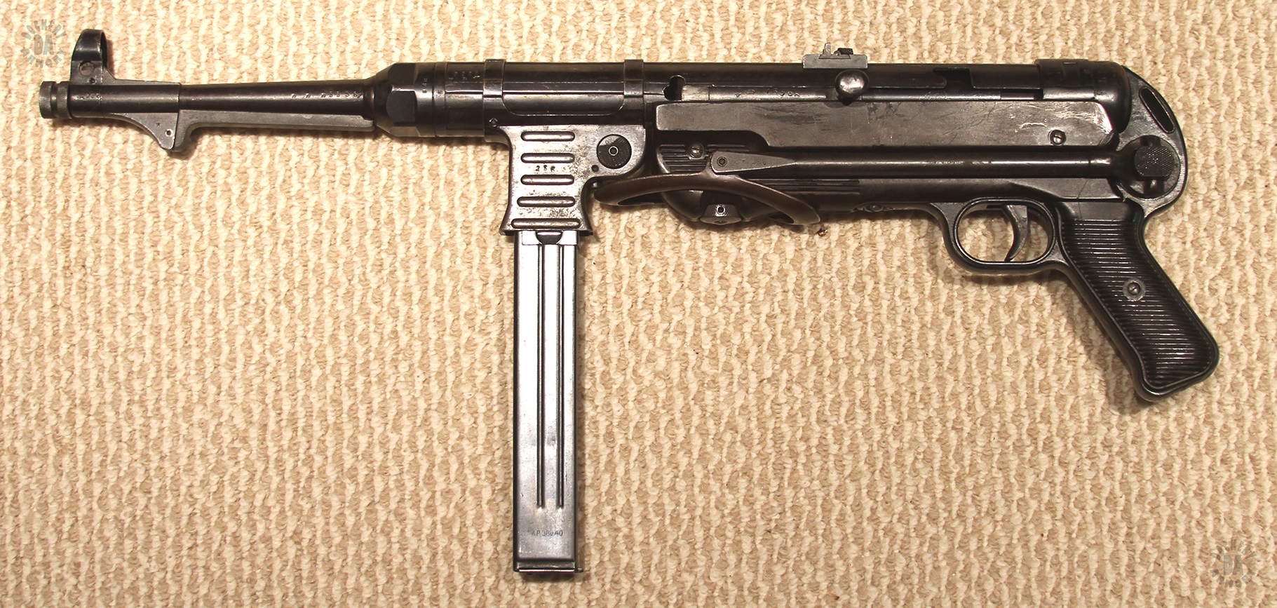
     This German submachinegun is probably one of the most recognized weapons of its type of World War II. Parts of the design were copied in a number of Allied weapons including the British Sten series, the Australian Austen, and the American M3 Greasegun, making the MP40 also one of the most influential designs of a submachinegun. At one point, the British even considered manufacturing the MP38 in 1940, just before the MP40 was available.

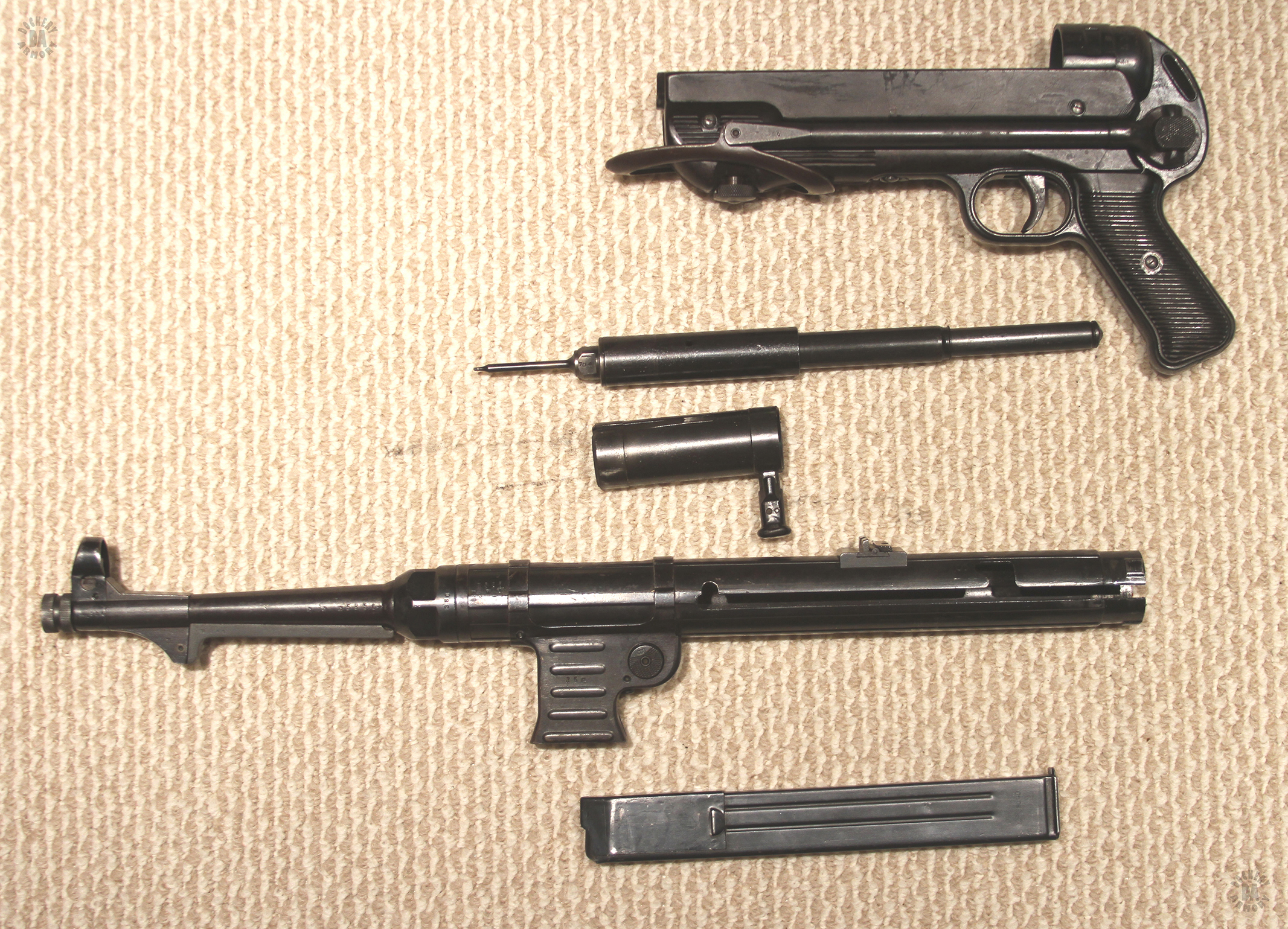
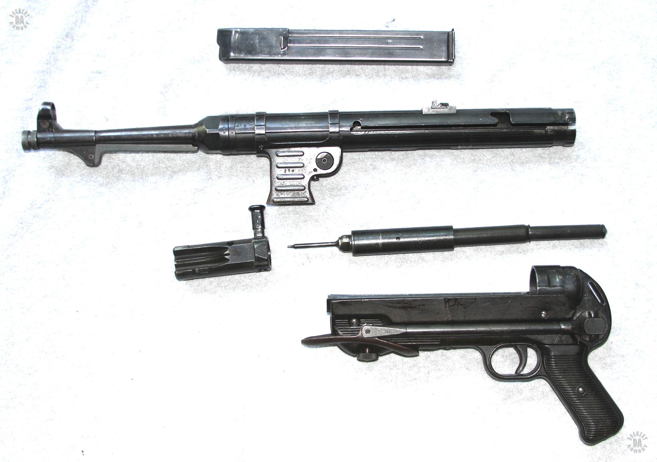
     The direct predecessor of the MP40 was the MP38. Though the earlier weapon was considered a very good design and proved itself on the battlefield, it was expensive and used a great deal of machinery to produce making it both time and labor intensive. The MP40 was a basic improvement on the MP38, particularly in that is used a great deal of stampings, pressings, and welding in its manufacture. These factors made it faster and easier to produce than the earlier design. Regular improvements were made to the internal components as well as some of the basic design of the MP40, improvements that continued to the final production units. These facts helped make the MP40 a turning point in the development and manufacture of submachineguns worldwide.

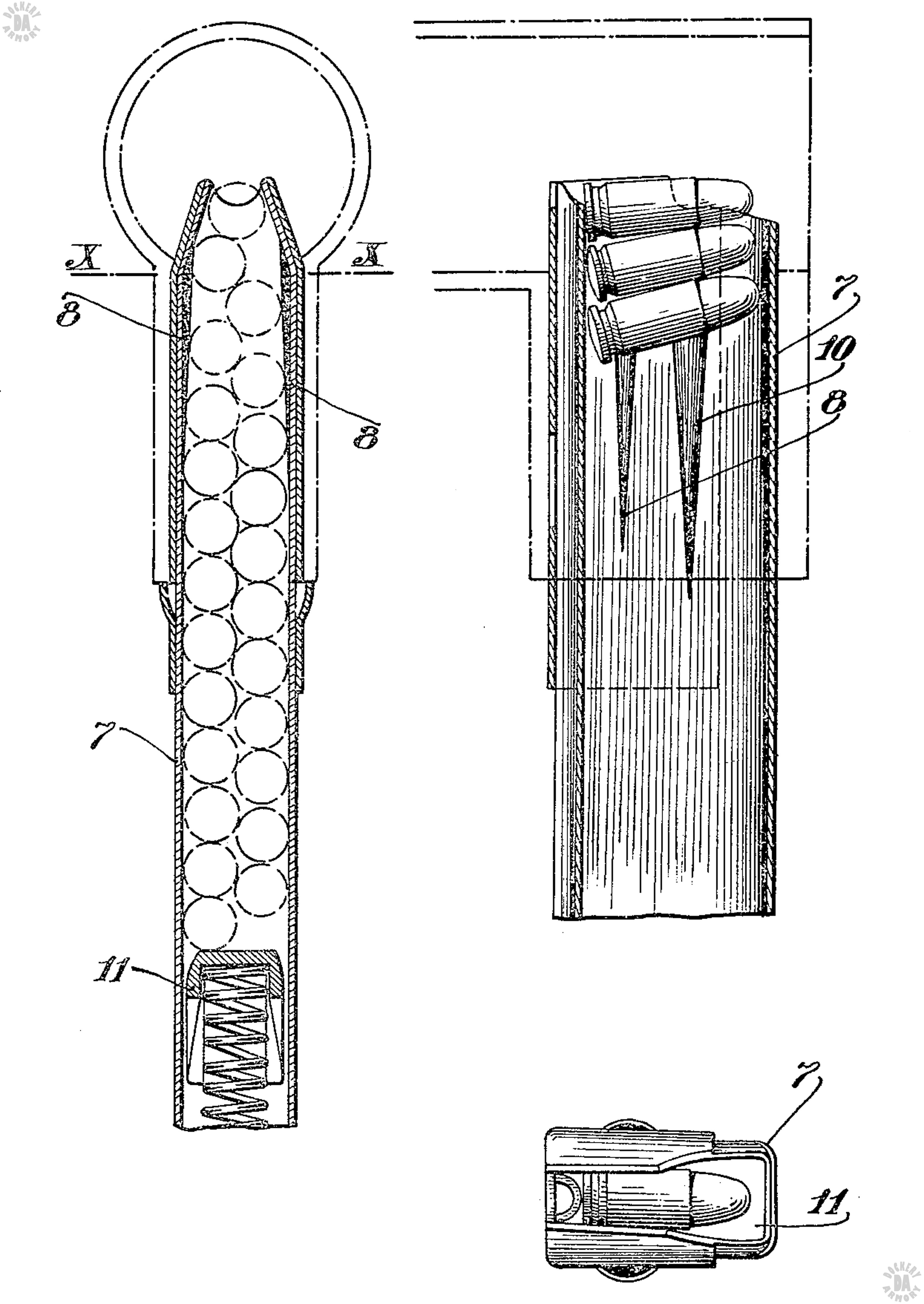
     In spite of the many positive features of the MP40, there were still problems with the design. The first of these centered on the magazine which were based on the earlier Hugo Schmeisser patents for a double column, single feed design. In the design, the cartridges sit in two rows down the body of the magazine. They are lifted into place by the follower spring where they meet the thick metal collar at the top. Near the top of the magazine the cartridges are forced against one another by the tapering sides of the magazine body. Each cartridge fits into a central feed opening for loading into the chamber. This setup makes it necessary to have a powerful follower spring to force the column of cartridges up and into position. This system makes it necessary for the user to have a magazine loader, a device that helps force the rounds down into the magazine when it is being loaded. Another piece of equipment that the operator has to keep track of. In a side pocket of one of the magazine pouches used with the weapon was a pocket to hold the magazine loader as well as a special magazine cleaning brush.

     The flat-sided magazines used in both the MP38 and the early MP 40 weapons operated fine, as long as they were clean. And gathering of dirt, dust, or grit inside the magazine body greatly increased the friction between the cartridges and the steel walls of the magazine. When troops operated from their barracks prior to World War II beginning, clean magazines were relatively easy. In the dirt and mud of active warfare, the gathering of grit within the magazines would cause critical failures to feed during combat. In August, 1942 orders went out that all magazines for the MP38 and MP40 would have two ribs impressed into the body of the magazine from both sides. This allowed debris a place to gather within the magazine and minimized the friction between the magazine walls and the follower. Additionally, in September, 1942, the magazine cleaning brush became available for issue.

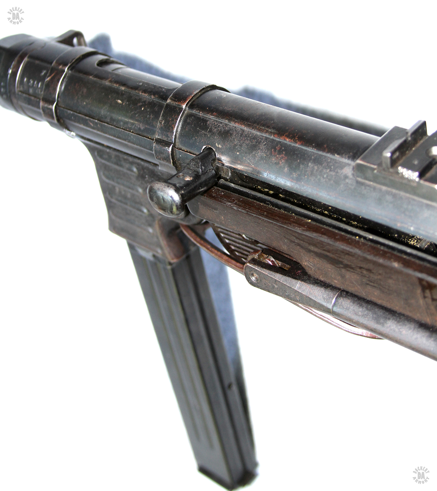
     Another critical action that caused jams with the double-column, single feed design was that the system was particularly sensitive to misalignment with the chamber of the weapon. Holding the magazine while firing was an easy way to damage the magazine or cause movement of the magazine, preventing and incoming round from properly chambering. Orders were issued that the only way to properly fire the MP38 and MP40 was to hold the weapon by either the ribbed bakelite forearm that covers the underside of the weapon and most of the frame behind the magazine housing, or by holding the magazine housing itself. To increase the strength of the magazine housing, by late 1941 five ribs had been stamped into the sides of the housing body. This also made firmly gripping the housing easier.

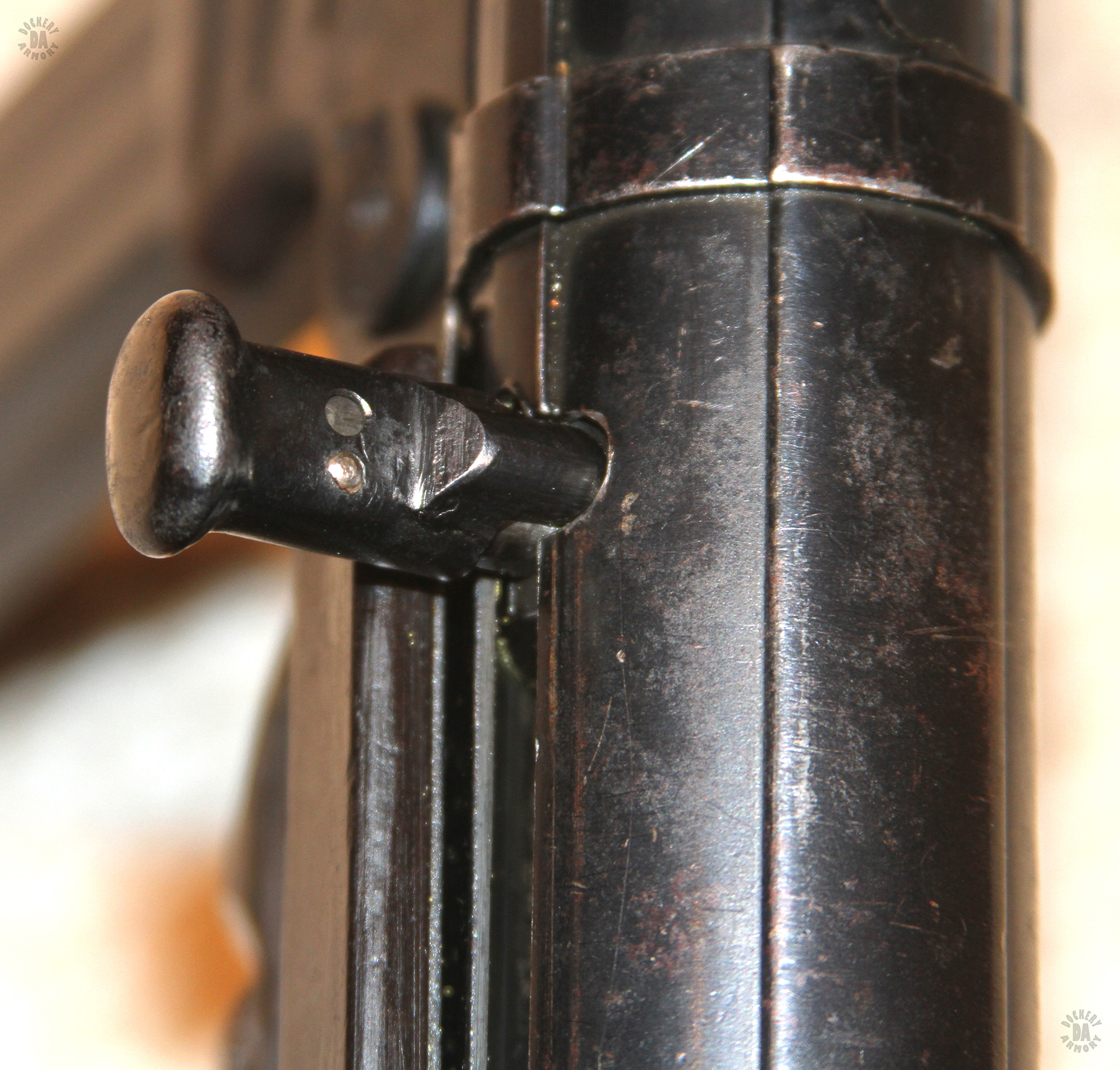
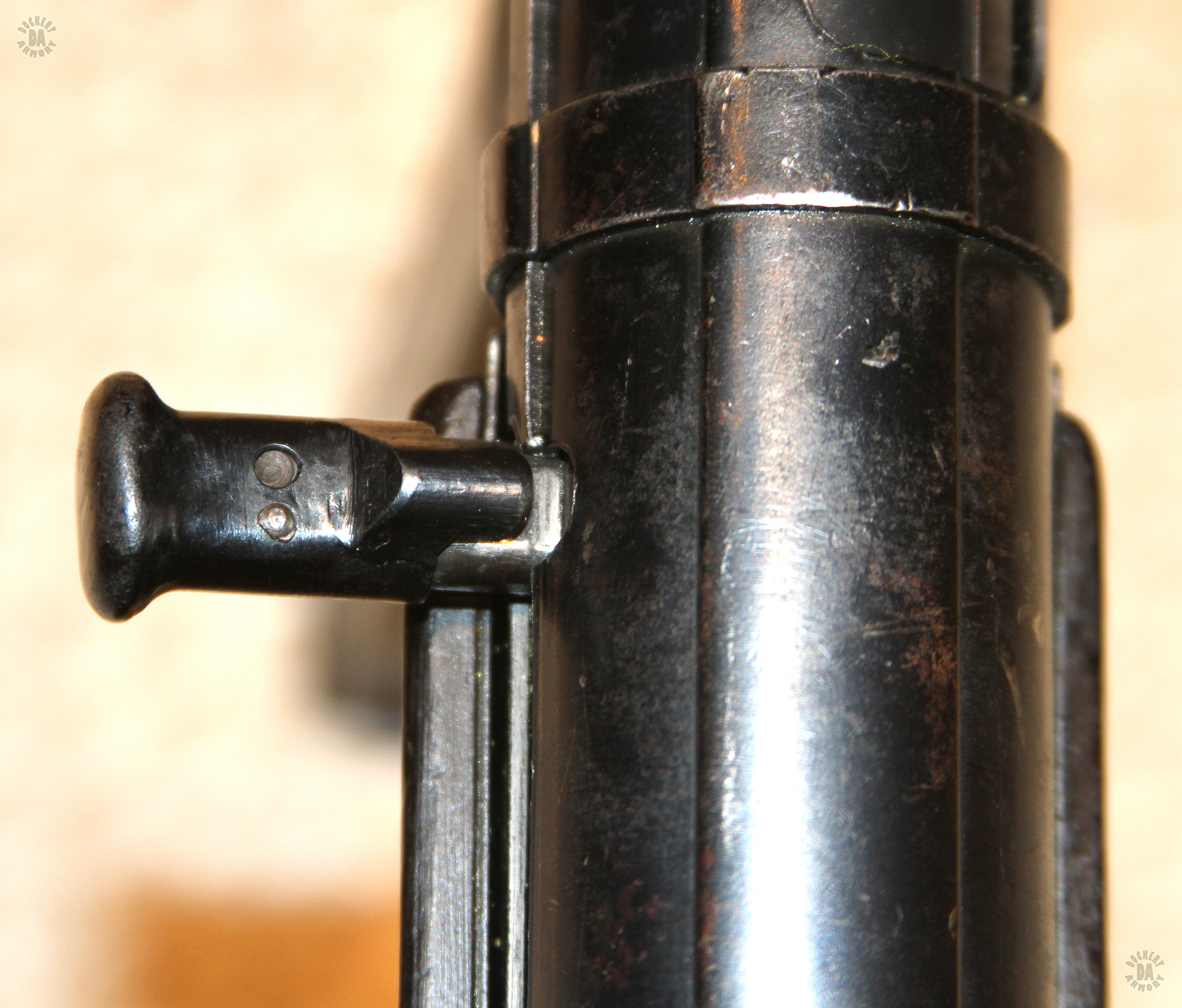
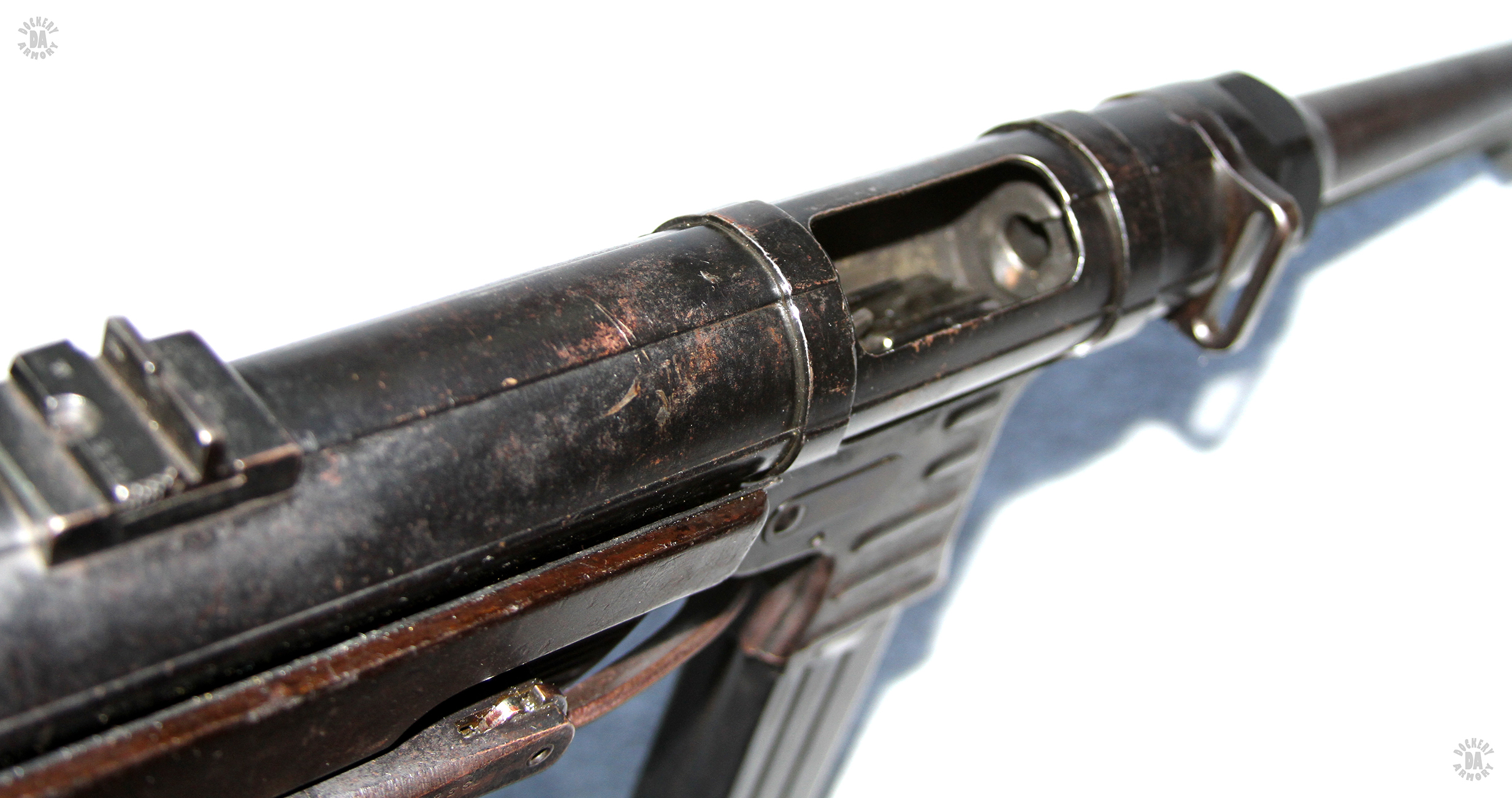
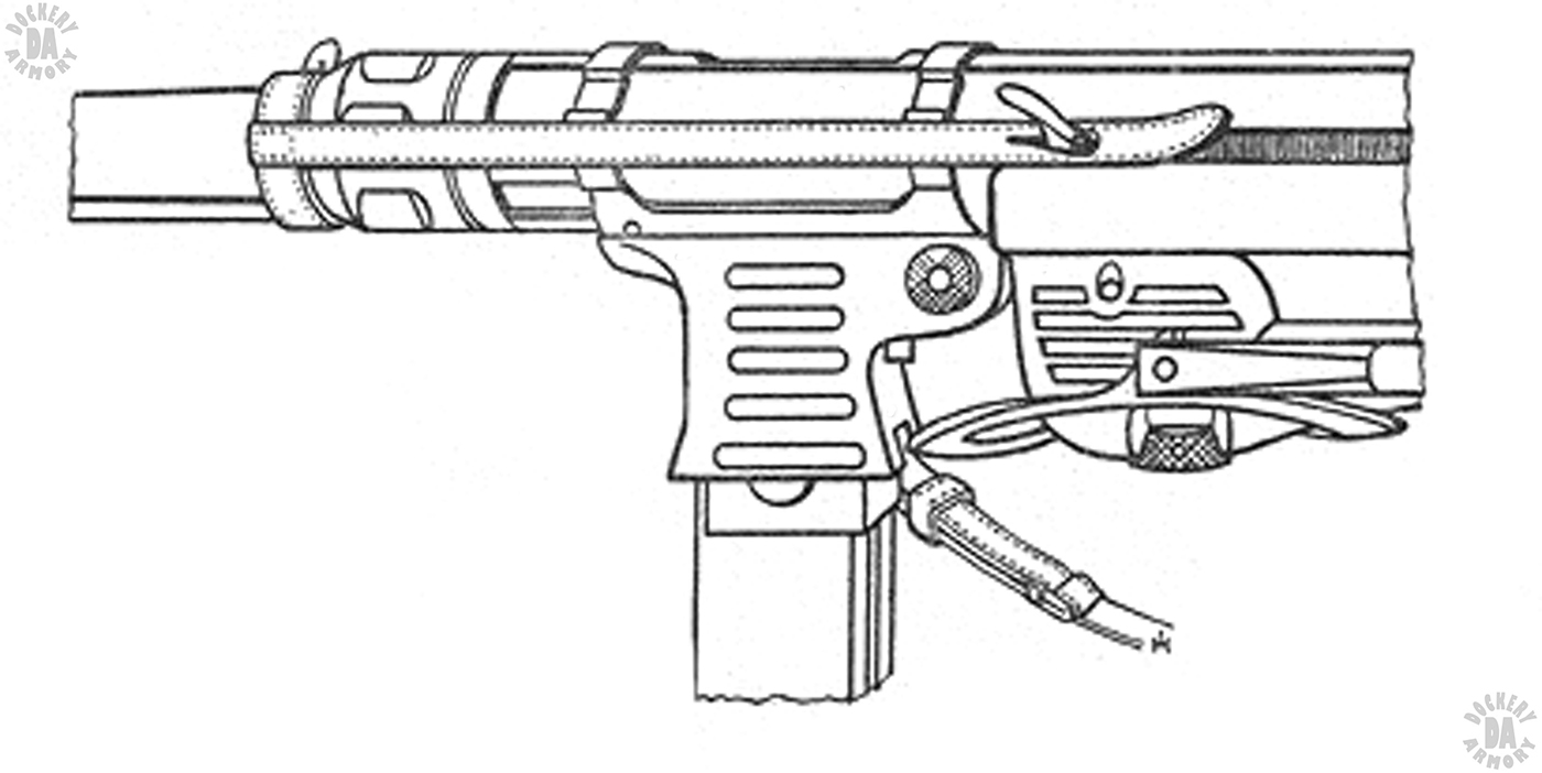
       One very important improvement to the MP40 was the addition of the two-piece cocking handle to the bolt. Early production MP40s utilized the same hook-shaped cocking handle as the MP38. Because of this it was often necessary to fit them with a locally produced (field made) safety strap that fit around the base of the barrel and had a thin strap that extended down the left side of the weapon. The end of the strap had a hole in it that could fit over the handle of the bolt, holding it forward and preventing accidental movement. The strap was made by unit armorers as it had to be replaced occasionally as it either burned through from the weapon firing or stretched out of shape from excessive wetting. It was not an elegant solution to the bolt movement and accidental discharge problem.

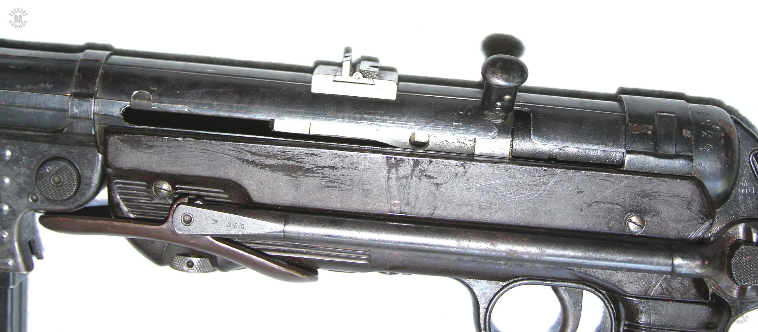
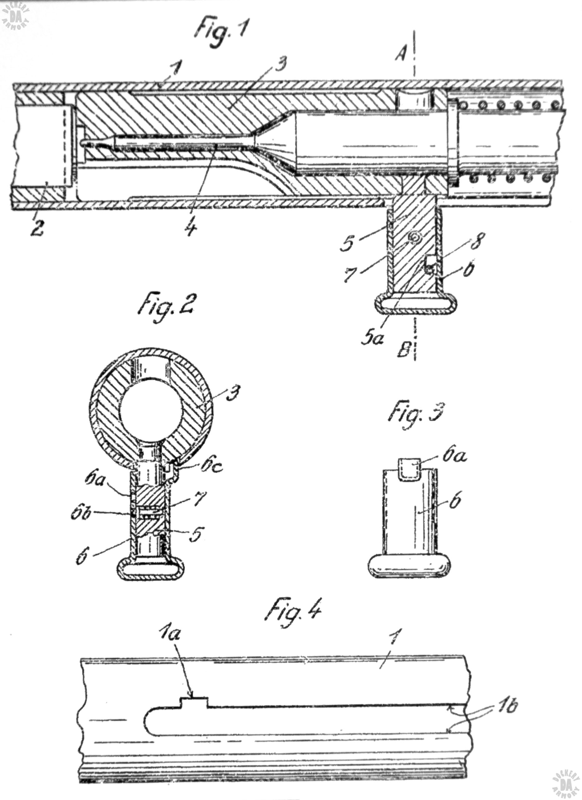
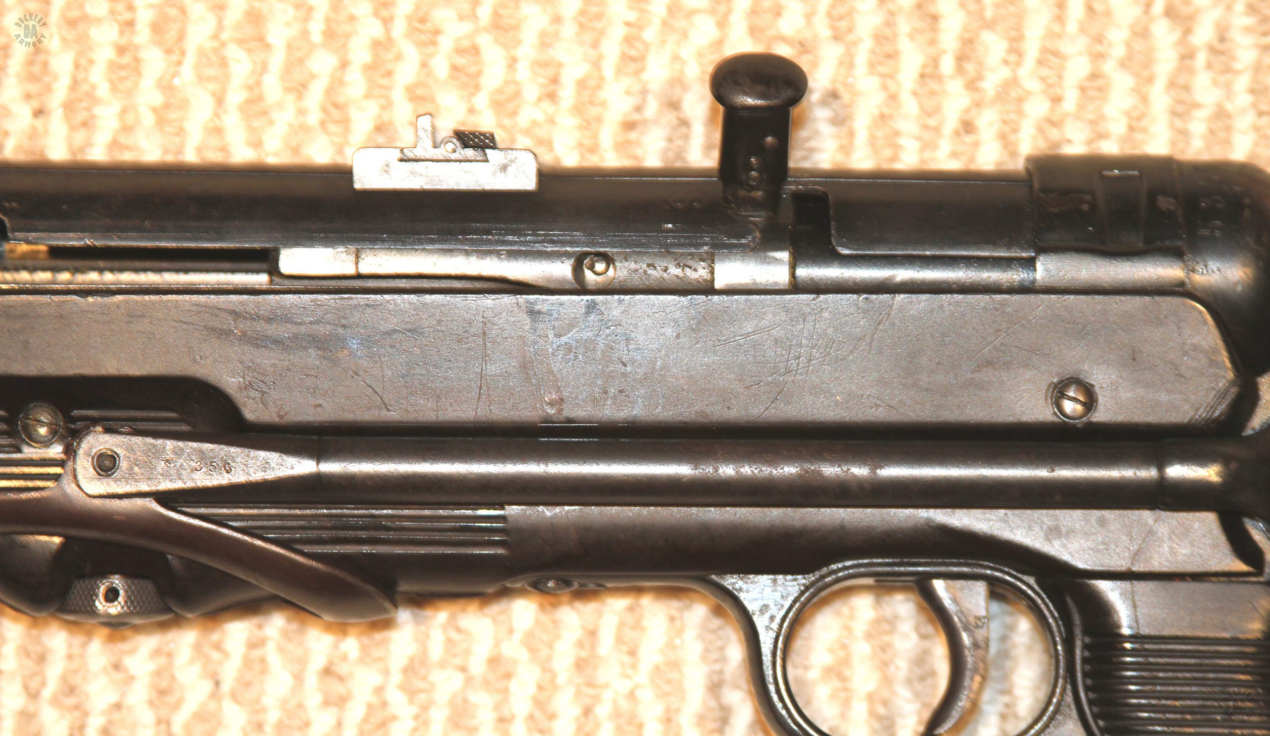
     A mechanical solution to the bolt movement problem was developed by Hugo Schmeisser in late 1940. By mid-1942, the cocking handle safety had become a standard feature of new-production MP40s. By late July, 1942, the Supreme Command of the (German) Armed Forces ordered that all original one-piece cocking handles on MP 40s and MP38s were to be replaced with the new safety handle. Technical instructions for the installation of the new part were issued in August 1942 for regimental workshops in the field.

     The new cocking handle safety used a two-piece cocking handle that could slide and lock into detents. On the upper side of the sliding handle was a lug that extended up and in from the body of the handle. In the receiver of the weapon was cut a small (7.2mm wide) notch with a curved (3.6mm diameter) notch at the upper front of the cocking handle slot. With the bolt in the forward position, pressing the cocking handle in snapped the lug into the notch, locking the bolt in place. The handle was easily pulled away from the weapon by the operator, releasing the bolt for cocking. The safety notch at the rear of the of the receiver was unchanged and the bolt would be pulled back and lifted (rotated) up and into the safety notch. Mainspring pressure kept the bolt handle forward in the extended top of the notch.

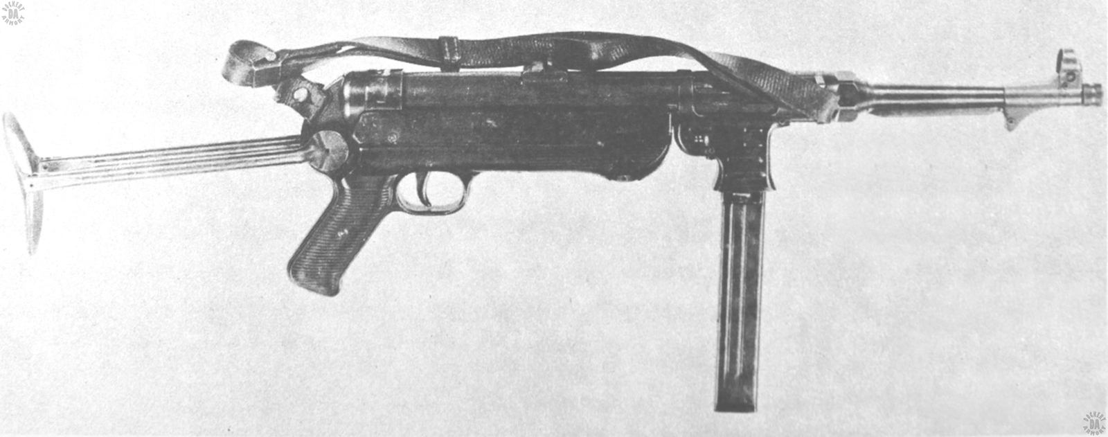
    The basic MP40 design allowed the operator to work the weapon completely without releasing his hold on the pistol grip. The weapon could be cocked with the left hand and the same hand could quickly change magazines. For accuracy, the stock would be unfolded and locked in the open position. But experienced shooters could quickly and accurately place their fire onto target with 100 yards by just holding the weapon with both hands.

     Continued minor improvements kept the MP 40 in front line service and full production until 1944. At that time, production was cut back so that facilities could be dedicated to producing the new Sturmgewehr StG44 assault rifle. Repairing battlefield damage and assembling weapon from stocked parts kept the MP40 in some form of production to the end of the war in 1945. By that time, well over 1 million MP 40s and MP38s had been produced. Steyr alone produced over half a million weapons of both types by the end of the war. Reportedly, though records are scarce, Steyr made over 46,000 MP40s in 1945, the last year of the war. Along with the weapons, over 15 million magazines were produced to feed the MP38s and MP40s.


A left-side view of the MP40 in its 1942 production version. The stock of the weapon is unfolded and locked into position for use. The bolt is in the forward position. This magazine also has a slight dent between the reinforcing ribs that is insufficient to prevent the magazine from being used. PHOTO CREDIT: Kevin Dockery

A close-up view of the two-piece cocking handle pressed in to the locked position. The upper lug on the moving portion of the handle is in the curved locking notch on the receiver. The round ball of the detent can be seen being pressed up by a small spring and keeping the moving handle locked in place. With the cocking handle in this position, the bolt is locked forward on the weapon and will not move due to a blow or jar, such as when a soldier drops his weapon or jumps from a vehicle. PHOTO CREDIT: Kevin Dockery

A close-up view of the locking cocking handle with the handle drawn out to operate the weapon. A space can be seen between the lug extension on the top of the handle and the matching cutout on the receiver. With the handle in this position, the bolt is free to move. PHOTO CREDIT: Kevin Dockery

A field-stripped view of the MP 40. Even when the magazine is included, the weapon is quickly broken down into only five major components. The telescoping mainspring assembly is second from the top with the firing pin on the tip plainly visible. The bolt, third from the top, in the same orientation that it would be when inserted into the weapon. The cocking handle is on the back of the bolt. Two raised bearing surfaces, on the front and back of the bolt, help guide it when the weapon is operated. The more open section in the model of the bolt allows some clearance for accumulated dirt or debris. PHOTO CREDIT: Kevin Dockery

A right-side view of an MP40 with the stock folded and a magazine locked into place. The bolt of the weapon is in the forward position. The value of the reinforcing ribs pressed into the sides of the magazine is shown in this picture. The dent on the side of the magazine, about 1/3 up from the bottom, would have possibly jammed the magazine is the ribs hadn’t prevented it from extending further. Such dents are common on weapon magazines used in combat and would have been much worse on the earlier flat-sided magazines. PHOTO CREDIT: Kevin Dockery

This instructional drawing was used by the US Army to show troops the various points of an MP40 submachinegun. The barrel rest is mis-identified in this picture which calls it a “cooling bar.” Of particular interest is the two drawings on the right side of the illustration. These two illustrations are of the MP40/I that utilized two 32-round magazines in its feed system. Though the MP40/I was relatively rare, it was considered important enough to illustrate it to the troops. PHOTO CREDIT: US Army

The bolt on this MP40 has been drawn back and rotated into the safety notch. The large engraved “S” on the front of the notch indicates the “Safe” position. In this location, the bolt handle has to only be drawn back a short distance, rotated down, moved forward, and the weapon is ready to fire. The rear sight blade with the knurled edges is folded down in the carry position. It is raised for shooting at 200 meters. The fixed rear sight blade is for shooting at 100 meters. Visible on several parts is the last few digits of the serial number. Even for a relatively quickly-built weapons such as a submachinegun, German manufacturers commonly put these numbers on parts to indicate the weapon they are fitted to. The three-winged stamp with’ in this case, the number “37” below it is the waffenamt stamp indicating the part was accepted for use. PHOTO CREDIT: Kevin Dockery

Looking in to the open breech of an MP40. This shows one of the drawbacks of an open bolt weapon, the very large hole that can allow dirt, snow, dust, or sand into the action at a very critical point. In its defense, the open breech design also allows a lot of air to circulate through the action and barrel, giving the system a chance to cool more easily between shots or firing. PHOTO CREDIT: Kevin Dockery

A side view of the two-piece cocking handle with the sliding portion pushed in to lock the bolt in the forward position. Since the MP40 fires from an open breech, with the bolt in the forward (fired) position, there cannot be a round in the chamber unless the weapon has had a serious malfunction. PHOTO CREDIT: Kevin Dockery

A field stripped view of the MP40, broken down into five main components. The knurled ring of the receiver lock is in the extended (unlocked) position on the underside of the bakelite forearm, inside the open portion of the folding stock’s buttplate. In this view, the underside of the bolt can be seen near the center of the picture. This shows the single-position feed for ammunition on the bolt with the central slot being for the ejector. PHOTO CREDIT: Kevin Dockery

Several of the drawings from US Patent Number 1,833,862 awarded to Hugo Schmeisser November 24, 1931 for his double-column, single feed magazine design. The difficulty with the design can be seen on the left with the double column of rounds being squeezed down to a single feed position. The single feed position for the ammunition is illustrated with the drawing at the lower right in the picture. PHOTO CREDIT: US Patent Office

One of the drawings from the French Patent Number 888.965 applied for by Hugo Schmeisser December 8, 1942 for his cocking handle safety for the MP40 submachinegun. Fig. 1 in the illustration shows how the device is specified for the MP40 submachinegun with that weapon’s bolt and internals being illustrated. The detents within the cocking handle safety are shown in Fig. 2. The outer, moving, part of the safety, including the extended safety lug, are in Fig 3 while the necessary notch in the cocking handle slot is shown in Fig. 4. PHOTO CREDIT: French Patent Office

A left-side view of the MP40 in it’s late 1942 version. The bolt is in the cocked position and the weapon is ready to fire. The folding stock is locked in the forward (folded) position. The five reinforcing ribs of the magazine housing are plainly visible. Of interest is the marking near the bottom of the magazine – “M.P 38u 40” for “Maschinen. Pistole 38 und 40.” this indicates that the magazine was made for use with the MP38 and the MP40. PHOTO CREDIT: Kevin Dockery

The bolt on this MP40 has been drawn back and rotated into the safety notch. In this position, the bolt handle has to only be drawn back a short distance, moved forward, and the weapon is ready to fire. The rear sight blade with the knurled edges is folded down in the carry position. It is raised for shooting at 200 meters. The fixed rear sight blade is for shooting at 100 meters. PHOTO CREDIT: Kevin Dockery

This drawing is from the official military Merkblatte (Leaflet) authorizing the field expedient fix for the safety problem on the MP38 and early MP40 submachine guns. It is interesting that this illustration shows the safety strap mounted on an MP40, recognizable by the smooth receiver and raised ribs on the magazine housing. Though it was a simple and effective solution to the problem of a moving bolt when the weapon was jarred, the safety strap was not recommended for use during combat operations. Without it, accidents could still occur. The leaflet was No. 985 and was issued in 1941. It is interesting that the leaflet was issued printed on pink paper to help make it stand out. PHOTO CREDIT: Germany

This MP40 has the long sling attached to the front and rear sling slots. The weapon can hang comfortable at the side of the operator. Additionally, with the front sling slot on the right side of the weapon, the submachinegun can be slung over the shoulder on the soldier’s back without the cocking handle digging into him. PHOTO CREDIT: US Army